The Importance of Vendor-Approved CAD Models
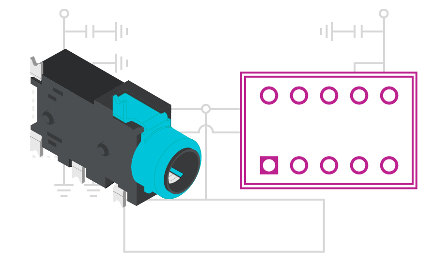
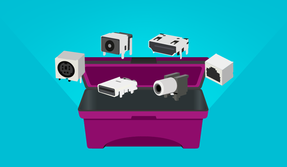
When designing a mechanical/electrical system, an engineer often relies on components from other vendors to complete their design. Whether it be electrical components needed for their PCBA or mechanical components for structural or fastening requirements, external components are critical to finishing out the project. Engineers rely heavily not only on detailed datasheets for component functionality, but also on CAD models for layout, schematics, and mechanical design. So that brings up the question, how does an engineer get the necessary CAD files for their project?
The History of CAD Models
Before CAD software was as common as it is today, engineers were frequently left with the task of generating their own CAD models by reviewing vendor drawings. While this was a way for the engineer to represent the component, it was somewhat limited to the level of dimensional detail provided on the drawing and assumptions often had to be made. A more severe limitation to this approach is time. As design cycles get shorter and engineers are facing more pressure to complete designs faster, spending a significant amount of time generating CAD models for these components is far from efficient.
Another common approach to addressing CAD needs is by outsourcing these requests to a third party to generate the files. While this can save the engineer time, it generally lacks the detail and accuracy of having the CAD files provided directly by the manufacturer. This regularly results in just a basic block for the 3D model. Although this will accurately depict the dimensional extremes of the part, it does not fully represent the part if there is a need to produce marketing data or realistic renders of the system. This means the engineer will still have to put a lot of work into the CAD model, and often times is forced to just recreate it from scratch depending on the quality of the model. This takes the engineer back to having to generate their own models to complete the design.
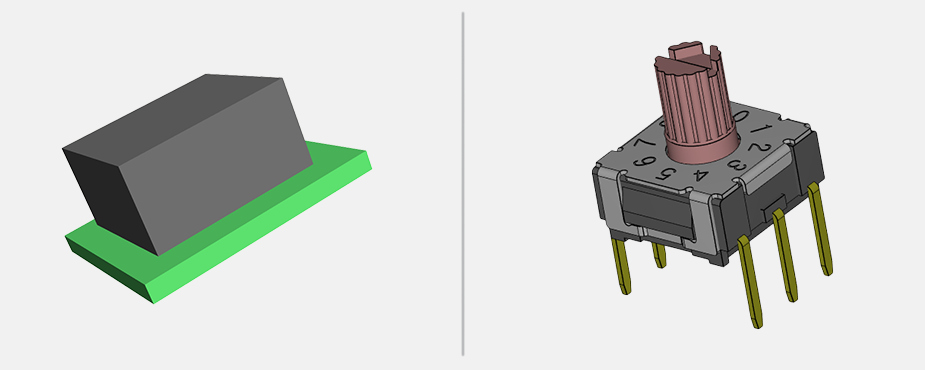
Similar to when 3D models lack the detail needed, the symbol and footprint quality can also be lacking. Often times, a symbol that is chosen is just a generic representation and does not follow industry-accepted standards for layout and design. While there are now several PCB CAD model libraries available online, many times the eCAD models are created on demand and can lack the manufacturer’s review to ensure their accuracy.
CUI Devices’ Commitment to CAD Models
The preferred method of CAD model design would be for the engineer to go directly to their vendor or an electronics design library to obtain vendor-approved CAD files for their design. However, this is not always available from the vendor, so the engineer is left to again either generate their own models or hope there is a CAD file available on the internet that they could use. CUI Devices recognizes the CAD needs for engineers and the pain points of not having accurate files readily accessible or having to generate their own files. As this is a priority for CUI Devices, we strive to produce 3D models as well as PCB footprints and symbols that accurately and aesthetically represent the actual product so the customer can easily insert the file into their system without having to worry about its accuracy.
We also work in partnership with SnapMagic who has a team of component engineers dedicated to producing high-quality PCB footprints and symbols available in over 10 different formats. All CAD models produced by SnapMagic follow the Institute of Electrical and Electronics Engineers IEEE-315 and IPC-7351B standards. IEEE-315 consists of graphic symbols that are easily recognized by engineers on the schematics, while IPC-7351B defines the land pattern geometries used to optimize land pattern and part dimensions to ensure proper manufacturing of solder joints.
SnapMagic also follows any unique guidelines provided by CUI Devices to ensure our CAD models are of high quality and meet the needs of customers. We take our 3D models and PCB footprints seriously and have quality checks in place to provide clear and accurate files. Our focus on the importance of these files is to give engineers peace of mind in knowing that what they receive is accurate and engineer-verified so that they can more quickly complete their design. A full library of our 3D models and PCB footprints streamlines this process, saving valuable time and resources.

