Connector CAD Models Help Accelerate the Design Process
Life seems to be placing ever-increasing demands on our time. Whether at home or at work, it feels like we have to run just to keep up. For engineers in the electronics industry, this is equally true, where looming project deadlines rank a close second to staying current with innovation as a competitive driver. On top of this, engineers are being asked to do even more with less resources and lesser amounts of time.
To combat these trends, engineers have found it essential to take advantage of all the tools available to them to streamline design cycles and reduce time-to-market. CAD tools are a case in point, having become the bread and butter of many engineers' daily routine. However, CAD tools by themselves do not provide the total answer, especially as the majority of design engineers have to contend with multiple CAD systems throughout the product lifecycle. In addition, modeling the individual components based on supplier specification drawings can be very time-consuming.
Consequently, it is not surprising that savvy engineers favor suppliers that offer ready-made 3D models for their components, whether these are sophisticated integrated circuits or simple passive devices such as resistors.
At CUI Devices, we seek to support design engineers through every phase of their project by offering a range of resources, including CAD models, for our entire product portfolio that encompasses audio components, encoders, thermal management devices, sensors, switches, and interconnect products.
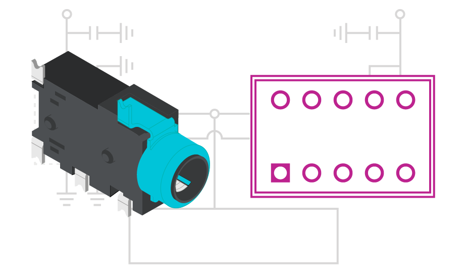
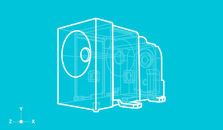
Mechanical models provide easy design visualization and validation
The ability to readily download free 2D and 3D mechanical models in popular CAD formats allows an engineer to easily see how components like connectors can be integrated into end-system designs. However, beyond saving the time it would otherwise take for an engineer to render suitable models themselves, supplier-provided models also deliver other benefits. First, a vendor's own model will accurately reflect its actual product, avoiding the possibility of errors in transcribing a component's dimensions from datasheet to model. Also, this accuracy will incorporate tolerances, ensuring that the component fits where it is supposed to, including, in the case of a connector, correctly mating with its counterpart.
Visualization, especially in 3D, not only helps the engineer implement their design, but it may also form part of a fuller rendering of the end-equipment. This may help "sell" the design to an end-customer or key stakeholder before ever getting to the point of producing a prototype. And, being able to tweak a concept at this stage can dramatically reduce the number of design iterations, saving both time and money. Other benefits can accrue further down the line, especially for an original equipment manufacturer (OEM) that may use more than one electronics manufacturing service (EMS). Here the ability to easily switch production locations is enhanced by component models that are compatible with the EMS' manufacturing tools. Not only does this save the system designer from having to re-render their model, with the obvious time and cost benefit, but it also avoids the risk of potential errors, especially if the target CAD tool is less familiar to the engineer.
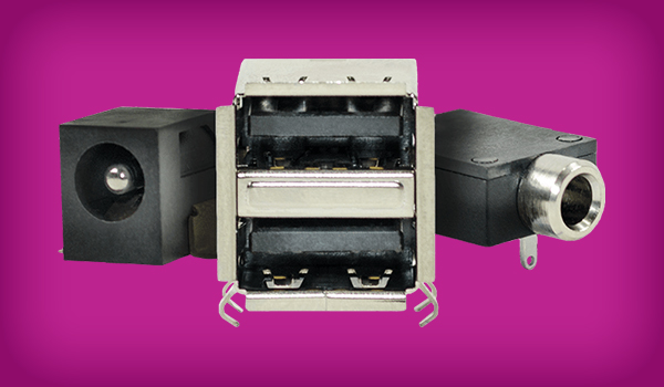
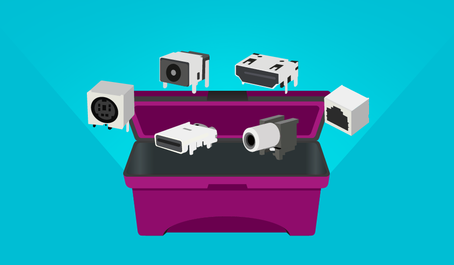
Ready-to-go connector CAD models
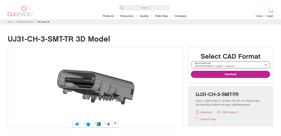
CUI Devices’ extensive portfolio of connectors includes audio, circular, dc power, USB, HDMI, memory card, modular, terminal blocks, PCB pins, pogo pins, DIN, and RCA versions. To support these product groups, we offer 3D CAD files as well as PCB footprints and symbols for hundreds of these individual connector models. They are available in most major CAD system formats, including: SolidWorks®, Pro/Engineer®, Autodesk Inventor®, Mechanical Desktop®, and many more.
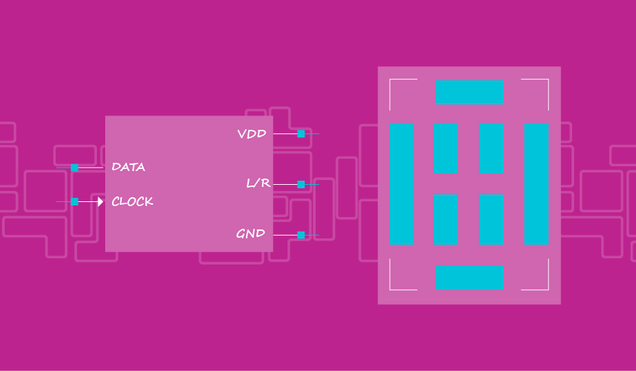
Every model in CUI Devices’ library can be previewed before downloading, with 2D views that include all six faces (front, back, top, bottom, left, and right) and a fully isometric 3D view. Various on-screen modes allow an engineer to zoom in and out, pan, tilt and rotate these views, and see them in different render modes – shaded, transparent, wireframe, etc. Once selected, and without the need for registration, the required CAD tool format can be selected and the model downloaded and dropped directly into the engineer's design.
Ready-available CAD models from component vendors can greatly improve efficiency during the design process, eliminating the mundane task of component rendering and allowing the engineer to focus on creating true value within his or her end-product while also reducing time to market.
 Tags:
Tags:
Additional Resources