What You Need to Know About USB Connectors and USB Cables
The term USB is short for Universal Serial Bus. As a quick refresher, a “bus” is a circuit arrangement or communication system that is used to transfer data between components in a system. A “serial” bus, in this case, transmits data one bit at a time over a single wire.
A USB connector, however, can not only carry data to and from components, but also electrical power, and can accommodate many different hardware devices, ranging from printers and keyboards to cell phones and flash drives.
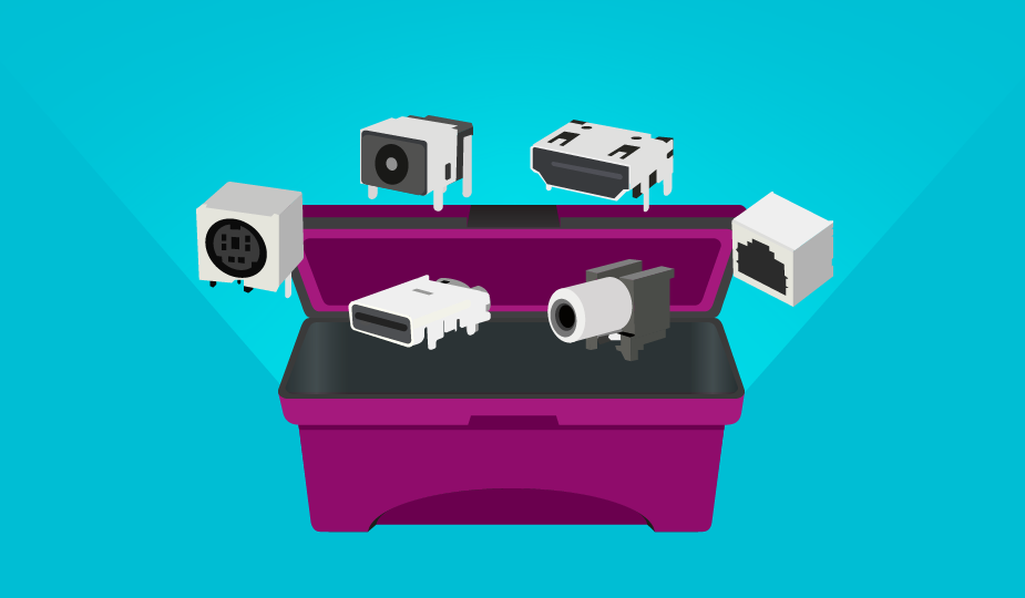
Prior to the development of the USB protocol, computers used both serial and parallel ports to accomplish data transfer, with individual devices employing various proprietary plugs, connectors, cables, expansion cards, and the necessary drivers. Data transfer rates were slow, with parallel ports running at about 100 kilobytes (kB) per second and serial at 115 to 450 kilobits (kb) per second.
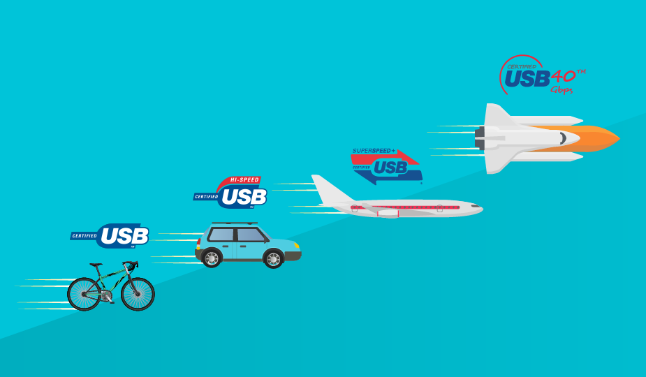
Debuting early in 1996, after much work by a consortium of companies, the USB 1.0 specification could initially transfer data at 1.5 megabits (Mbit) per second at low speed and 12 Mbit per second at full speed. Transfer speed was further increased with the release of USB 2.0 in the year 2000 at 480 Mbit per second, and USB 3.0 in 2008 at 4.8 gigabits per second (Gbps). USB 3.2 has taken over the 3.1 and 3.0 standards and covers speeds up to 20 Gbps and is currently the most commonly available. The latest version is USB4, released in 2019 with transfer speeds up to 40 Gbps and is slowly being introduced into common usage.
The USB standard has been guided and certified over the years by the USB Implementers Forum (USB-IF), which has more than 700 companies as members. The work of the USB-IF has led to a series of releases of the standard over the years with faster and faster specs. This increased speed and video resolution via a small and inexpensive interface has made USB connectors the dominant signal transfer technology in use around the world today. Shop CUI Devices' full range of USB connectors and USB cable assemblies.
USB Physical Form Factors
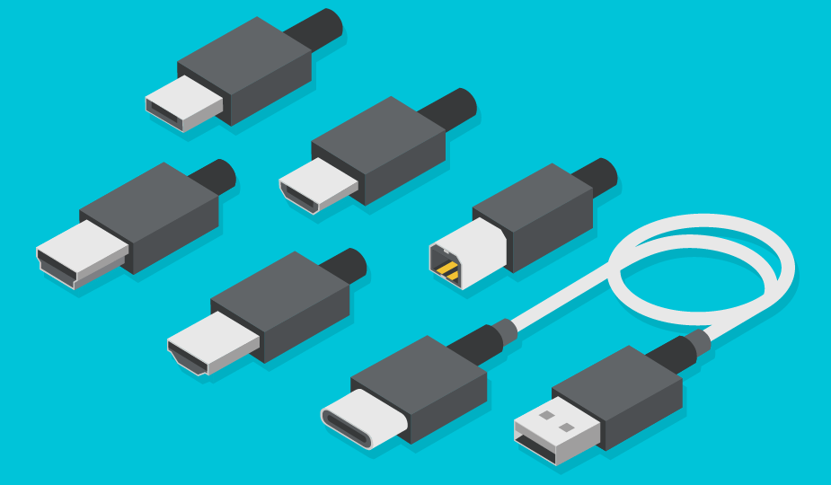
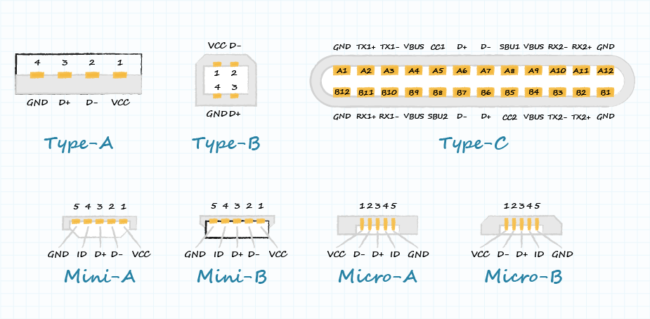
There are several types or physical form factors of USB connectors that are available for use in a variety of applications. These include:
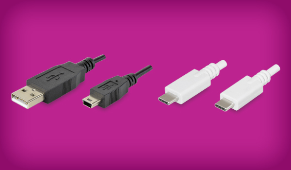
- Type A – This is the original, most common USB connector, also called USB Standard A. It is used to connect downstream peripherals to a host device. The flat, rectangular shape is held in place by friction making for ease of insertion and removal. It provides 5 V dc power on one of the pins and is compatible with all types of USB protocols.
- Type B – The Type B connector is most often associated with USB computer peripheral devices. This connector is square in shape, with slightly beveled corners on the top. Like Type A, it is held in place by friction. It was developed to allow peripherals to be connected without the risk of connecting two host computers to each other. This connector type is still in use, but the micro version is more prevalent.
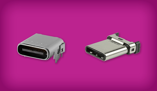
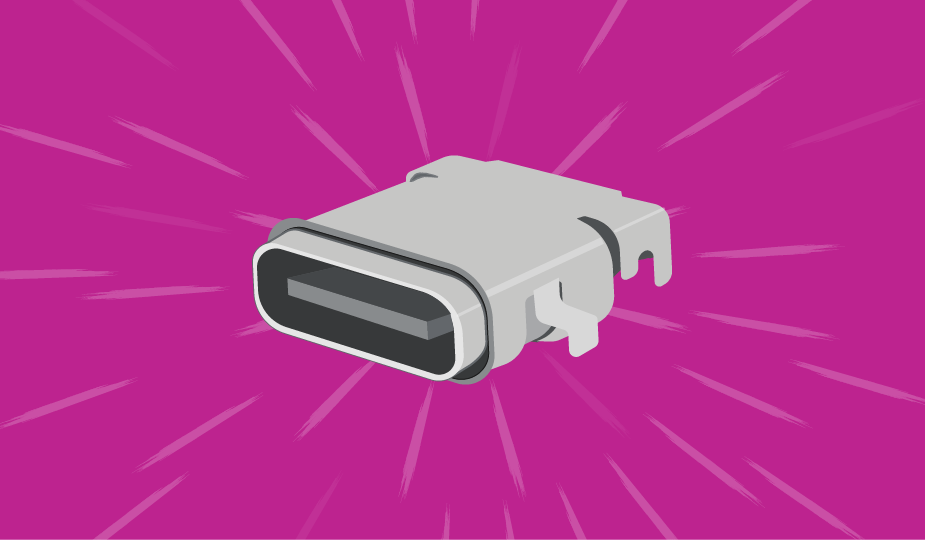
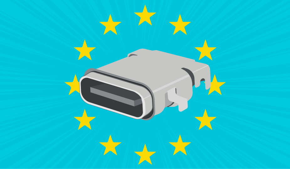
- Type C – This is the newest USB interface, with a reversible symmetrical design that can be inserted with either side up and can be plugged into any USB-C device using either end of the cable. It can carry USB 3.2 (previously 3.1 and 3.0), 2.0, and 1.1 signals and can transmit data at up to 20 Gbps with power delivery up to 100 W in either direction (expanded to 240 W with USB PD 3.1) and can support DisplayPort video and four channel audio. Type C also supports USB4 as well as Thunderbolt, a hardware interface allowing the connection of peripherals to a computer with data transfer speeds up to 40 Gbps.
- Micro & Mini A&B – As the name implies, these are smaller form versions of Types A & B connectors that offer a physically smaller connection while maintaining high speed transfer rates of 480 Mbps and On-The-Go (OTG) features, allowing mobile devices and other peripherals to act as a USB host.
- Type AB – This connector allows both micro A and micro B plugs to connect to this single receptacle type, providing greater flexibility.
The individual types of USB connectors can only mate with their associated male or female connectors. There is no cross compatibility. But while the connectors themselves are standard, the enclosures in which they are used can be changed significantly for different applications. This has led to the development of IP rated (Ingress Protection) USB connectors that enable robust protection against solid or liquid intrusion into devices used in harsh environments.
Most USB cable assemblies also have one type of connector on one end and a different type on the other end, Type A to Type B or Type C is very common. As Type C is designed specifically to be interchangeable, it is more common for Type C to be on both ends of a cable and will grow in usage as Type C ports are more widely adopted. USB 3.0 micro B plugs, which have a wider connection to accommodate the greater data transfer rate, cannot be used with a USB 2.0 micro B socket. However, devices with USB 3.0 micro B ports can be mated with older USB 2.0 micro B type male plugs.

USB Communication Standard Versions
As has been noted, the USB communication standard defines the data transmission speed, handshake protocols, and power supply specs between the devices being used. There have been significant improvements of the standard over the years, with data transfer speeds ranging from USB 1.0 at 1.5 Mbit per second to USB 3.2 with speeds up to 20 Gbps, and now USB4 with speeds up to 40 Gbps. Each succeeding version facilitates a new round of interconnect hardware.
USB communication standards are notoriously confusing with frequent retroactive naming changes, but currently USB 3.2 is the most readily available USB standard that is compatible with both Type A and Type C connectors, though it can vary from 5 Gbps up to 20 Gbps. The 20 Gbps standard can also be known as “SuperSpeed USB 20 Gbps” or “USB 3.2 Gen 2x2”, where the 10 Gbps standard can also be known as “SuperSpeed USB 10 Gbps” or “USB 3.2 Gen 2.” Finally, the 5 Gbps standard is currently known as “SuperSpeed USB 5 Gbps” or “USB 3.2 Gen 1.” However, the usage of older naming conventions can be found throughout the internet, and it may be easiest to manually check the speed ratings for the device or connector and use that as the baseline. Check out our blog post, The History of USB Standards from 1.0 to USB4, for more information.
| Name | Maximum Speed | Alternate Name | Previous Name |
|---|---|---|---|
| USB 3.2 Gen 2x2 | 20 Gbps | SuperSpeed USB 20 Gbps | USB 3.2 |
| USB 3.2 Gen 2 | 10 Gbps | SuperSpeed USB 10 Gbps | USB 3.1 Gen 2 |
| USB 3.2 Gen 1 | 5 Gbps | SuperSpeed USB 5 Gbps | USB 3.1 Gen 1 or USB 3.0 |
However, as is the case with many installations, different versions often come into use in the same system. If devices using a newer USB version and an older version are communicating, they will default to the older version and speed. This is a function of the software, but compatibility with the standard is also hardware related.
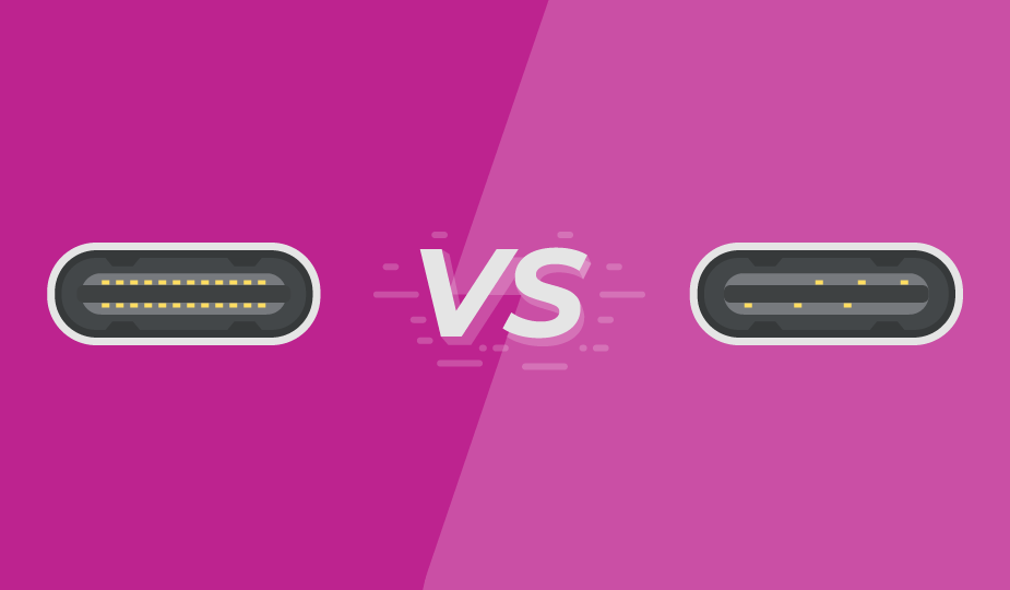
All Type C connectors are compatible with USB 3.2, though some Type C connectors still conform to earlier standards. Type A and B is dependent on the cable, with different connector colors typically denoting different versions for quick reference. Confusion can often arise when looking at the relationship between the physical connector standard and communication standards. Our blog post, USB Type C and USB 3.2 – Clarifying the Connection, discusses this in more detail.
With the original standard, a host was required. A Type A connector usually indicated the host device, and a Type B usually was connected to the peripheral. With USB OTG (On The GO), this is not necessary. USB OTG is a specification that allows a USB device (such as a smartphone) to act as a host, allowing other USB devices to be connected. Basically, it allows a USB device to read data from other devices without requiring a computer.
USB Power Delivery Standards
The USB standard began as a data interface protocol to simplify interconnectivity between devices, and it supplied some power. It has since matured from a data interface supplying limited power to a significant power conduit that includes a data interface. Numerous devices are now able to charge or receive power through the connection.
A concerted effort has been made to standardize the transmission of power and increase the feature set in the form of the USB Power Delivery (USB PD) standard. Using Type C, USB PD can provide variable voltage up to 20 V and a maximum current up to 5 A, with an overall limit of up to 100 W of power transfer. The USB PD 3.1 standard, released in 2021, has since expanded that power transfer capability up to 240 W. Additionally, the direction of the power is no longer fixed, with either the host or the peripheral supplying the power. Power management can also be optimized across multiple peripherals.
USB PD requires a digital device handshake to achieve these higher ratings. If the requisite chips are not available and the handshake does not occur, the system will revert to the 5 V/1 A standard. This is independent of the USB version and type but does require the type to support the USB PD standards. For example, a Type A to Type C cable that supports versions 2.0 and newer can use PD.
Progression of USB Power Delivery specifications
| Specification | Maximum Power | Maximum Voltage | Maximum Current |
|---|---|---|---|
| USB 2.0 | 2.5 W | 5 V | 500 mA |
| USB 3.0 and 3.1 | 4.5 W | 5 V | 900 mA |
| USB BC 1.2 | 7.5 W | 5 V | 1.5 A |
| USB Type-C 1.2 | 15 W | 5 V | 3 A |
| USB PD 3.0 | 100 W | 5/9/15/20 V | 5 A |
| USB PD 3.1 | 240 W | 28/36/48 V | 5 A |
PD can also work with devices that do not transfer data, utilizing USB purely for power. It does require separate communication lines for power negotiation and therefore is slightly more complicated to design and manufacture than many non-USB formats. This complication can be outweighed by the fact that PD creates a charging standard across a large array of devices, simplifying and consolidating chargers. This can reduce e-waste and the inconvenience of needing multiple cables for different devices. To learn more, read our Introduction to Power-Only USB Type C connectors blog post.
USB Applications Continue to Expand
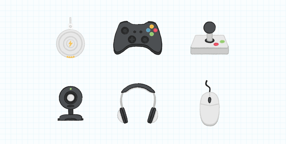
By offering a small form factor, ease of design and use, high communication speeds, plus increased power transfer, USB connectors can be used in a very wide and growing list of applications. A short list of these uses includes:
- Desktop and laptop computers
- Disk drives
- Printers
- Scanners
- Joysticks and controllers
- Video cameras
- Mobile phones, Smart TVs
- Gaming consoles
Since data transfer is not a requirement, USB connectors can also be used solely to power devices such as rechargeable flashlights, charging pads, and many other portable consumer devices.
The robustness and speed of the newest USB standard is also opening even further applications. It now has the bandwidth, reliability, and power delivery capability to be used in industrial applications such as data acquisition and monitoring, machine vision, and process control. Basically, any application that uses 240 W of power or less can be a candidate for USB power.
Summary
USB is an incredibly flexible standard that is approaching nearly universal adoption in areas where data transfer, along with power, is required. USB connectors and cable assemblies combine ease of use along with intelligent technical specifications to allow the product or systems designer to lower cabling needs and clutter, reduce footprint, ensure backward compatibility, and trim overall costs. Whether designing for the future or interfacing with legacy products, understanding the capabilities of USB will help designers to create products that can be used by nearly anyone on the planet.
 Tags:
Tags:
Additional Resources