The Ultimate Guide to RJ45 Connectors
The use of modular electronic connectors has been one factor in the explosion of communication and data services around the world. One of the most widely used types in the modular family of devices is the RJ45 connector.
As we have learned in another blog topic, the modular connector system was developed by AT&T in the 1960’s and 1970’s to take the place of bulky phone connectors and their labor-intensive installation. This new connector system offered simple, quick, and convenient setup that could be customized on-site by a technician or installed by the user in the home. The line has expanded over the years to include data communication mainstays, like the RJ45, which was developed for computer networking. In fact, RJ45 connectors are commonly referred to as Ethernet Connectors.
What is an RJ45 Connector?
An RJ45 connector is a commonly used modular interconnection device matched with a cable to provide data communication service to various electronic devices and systems.
The various connectors developed using this system were categorized by the FCC in 1976 into the Registered Jack (RJ) system, giving rise to the RJ label. This was done to ensure compatibility between phone company hardware and consumer equipment. The RJ system covers the physical connector, wiring patterns, and signal specifics.
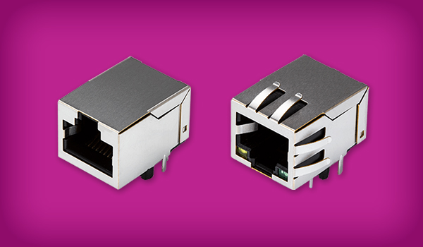
RJ45 devices, like all modular connectors, contain metal contacts separated by insulating plastic channels. The channels fit into a matching socket and the connectors lock in place with a tab making them secure but also removable. Internally, RJ45 devices contain 8 pins and 8 wire positions used to handle signals or power, so they can accommodate 4 twisted wire pairs.
This 8-pin configuration of an RJ45 is similar to that of 8P8C connectors, but true RJ45 connectors also include a tab that only allows insertion of the device in one orientation with a compatible socket to avoid an improper wiring connection. Hence, an RJ45 is one type of an 8P8C connector. However, in common use most 8P8C connectors are referred to as RJ45, but this is not quite accurate. You can plug 8P8C connectors into RJ45 sockets, but you cannot do the reverse.
RJ45 Features and Capabilities
RJ45 connectors incorporate the basic features of modular connectors: low cost, solderless assembly of connector and wiring, quick production of custom cables, simple insertion and removal, easy field assembly with simple tooling, and the ability to customize cables on-site. Sockets (or receptacles) can also have a vertical or horizontal orientation, allowing their use in various applications.
Beyond this, RJ45 connectors also feature the aforementioned orientation tab to prevent incorrect wiring. Their 8-pin configuration also means that they can be used in more demanding and data-intensive applications.
Additional available features can include:
- Shielding - to cancel the effects of EMI/RFI
- Keying - to ensure proper insertion
- Various mounting capabilities - to allow for panel, board, surface or through hole methods
- Displays and indicators - to indicate connection status
- Integrated magnetics - to allow for better shielding plus current protection
- Hi-Rel - to provide protection for the hardware and the connection
Applicable Standards of the RJ45 Connector
There are several engineering standards that apply to RJ45 connectors, depending on their application. ANSI/TIA 1096-A covers the basic physical dimensions, mechanical characteristics, and contact requirements for RJ45 devices. The basic wiring standards T-568A and T-568B cover RJ45 wiring and pinouts. IEEE standards 802.3at, 802.3af and 802.3bt cover Ethernet specifics and details for power over Ethernet (PoE) devices, where the connector supplies electrical current to the end device. IEEE 1394 defines the data interface bus structure used with RJ45 devices. Various other standards cover the cables or wiring used with RJ45 devices, again largely depending on the specific application. We will cover several of these standards in greater detail below.
Current Uses of RJ45 Devices
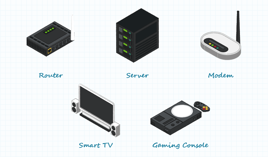
RJ45 devices are chiefly used to connect an internet-enabled device (such as a PC) with another network device such as a server, router, modem, smart TV, gaming console, and other devices that use the Ethernet protocol. Ethernet networks are common in both professional and domestic environments. Hardwiring using RJ45 devices enables higher data speeds with stability and security of data transfer, making them also attractive for use in industry and on the factory floor.
Ruggedized RJ45 technology is also finding increasing use in data communication applications that expose the system components to moisture, dust, vibration, chemicals, or mechanical stress. Various additional features of the connectors like boots or strain reliefs allow for the performance necessary to survive in these environments.
RJ45 and Ethernet
Ethernet is simply a way of connecting computers and other devices within a physical space. It enables the transmission of data over a Local Area Network (LAN) or Wide Area Network (WAN) and connects them via cable allowing them to communicate with each other.
The Ethernet standard (IEEE 802.3) was developed by the Institute of Electrical and Electronic Engineers (IEEE) in the 1980s and is presently the most popular LAN technology in use worldwide. It defines the rules for configuring an Ethernet network (connections), the number of conductors that are required for a connection, the expected performance, and a framework for data transmission.
The wide acceptance of Ethernet technology is due to the balance it offers between ease of installation, speed, cost, and broad network protocol support. RJ45 connectors are the standard devices used in network set-up.
What is EtherCAT?
EtherCAT is short for Ethernet for Control Automation Technology. It was introduced in 2003 and is defined by the International Electrotechnical Commission (IEC) standard 61158. It is a highly flexible network protocol used by industry for real time factory automation, test and measurement, and other applications. It operates at high speed and is very efficient. Again, RJ45 connectors are used in implementation of an EtherCAT network. No other special hardware is required. Devices in an EtherCAT network have two RJ45 ports, one connected to the previous node in the network and one connected to the next node. This allows for efficient use of bandwidth.
Cat5 vs. Cat6 Cabling
The cabling used in Ethernet and EtherCAT networks is available in different versions. Cat5 and Cat6 cables are both used to connect computers in a network, but their performance greatly differs.
Cat5 is made of 4 twisted pairs of wire and, while widely used in the past, is becoming obsolete due to the Cat5e cable. Cat5e is also made of 4 twisted pairs of wire but due to design changes is up to 10X faster than Cat5 and offers greater resistance to crosstalk, or interference.
Cat6 is also made from 4 twisted pairs, but is faster than Cat5e, has greater bandwidth capacity and functionality, reduces crosstalk or interference via shielding, and is backwards compatible with Cat5 and Cat5e. Cat6 cable is typically used in network installations that reach Gigabit speeds. The newer Cat6a cable adds thick plastic casing to further reduce crosstalk and can be used for longer cable runs (up to 328 feet). Cat7 cable incrementally improves bandwidth.
| Cable Type | Maximum Speed | Maximum Bandwidth |
|---|---|---|
| Cat 5 | 100 Mbps | 100 MHz |
| Cat 5e | 1,000 Mbps | 100 MHz |
| Cat 6 | 1,000 Mbps | 250 MHz |
| Cat 6a | 10,000 Mbps | 500 MHz |
| Cat 7 | 10,000 Mbps | 600 MHz |
| Cat 7a | 10,000 Mbps | 1,000 MHz |
Remember that each of these cable designs operates with 4 twisted pairs, or eight wires, hence the necessity of RJ45 connectors with 8 pins to connect all those wires. All Cat5, Cat5e, Cat6, Cat6a, Cat7, and Cat7a cables use the same RJ45 connectors.
Power Over Ethernet (PoE) and RJ45
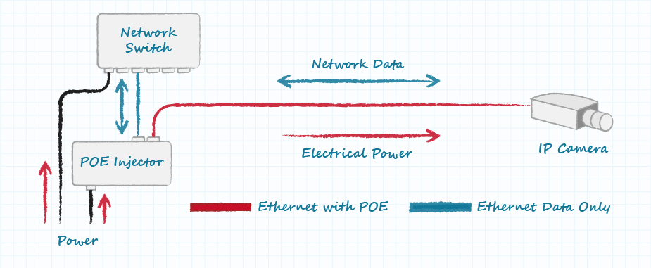
Modular connectors like the RJ45 also offer the ability to relay both signals and deliver electrical power to the devices being connected. Power Over Ethernet (PoE) is a technique for supplying dc power to devices over the unused twisted pairs in Ethernet cables, eliminating the need for separate power wiring. PoE is governed by IEEE standard 802.3af and subsequent versions that have raised the power delivery. The various versions are:
| Nomenclature | Standard | Maximum Power |
|---|---|---|
| PoE | IEEE 802.3af | Up to 15.4 W |
| PoE+ | IEEE 802.3at (Type 2) | Up to 30 W |
| PoE++ | IEEE 802.3bt (Type 3) | Up to 60 W |
| PoE++ | IEEE 802.3bt (Type 4) | Up to 100 W |
The usage of PoE has grown rapidly due to cost savings based on no need for separate electrical cables, outlets, or installation fees. It also offers flexibility since devices do not need to be located near electric outlets. It is also designed to be safe, reliable, and scalable.
RJ45 Technical Specifics/Board Layout Considerations
If you are designing a device that will interface with an Ethernet network and use RJ45 connectors, there are some technical considerations depending on your level of design involvement.
At the board level the focus is on reducing EMI, maintaining signal integrity, and preserving electrical signal isolation. Without getting into the details of circuit design, attention must be paid to the length and position of traces on the board. Magnetics should also be isolated and kept as close as possible to the RJ45 connections. Ideally, RJ45 connectors with integrated magnetics would be best to reduce EMI, which is discussed in more depth below. Physical placement of the connectors on the board must also be considered.
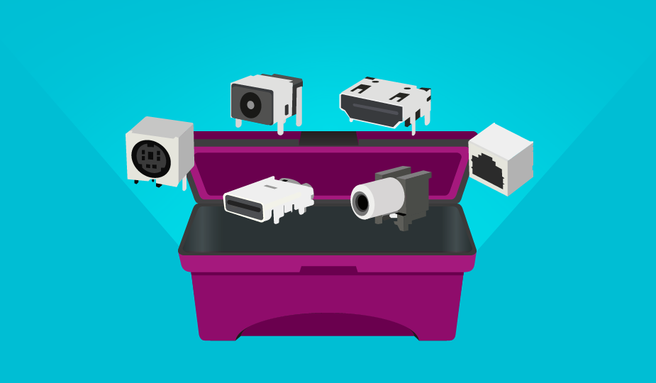
RJ45 connectors are available for most standard component mounting methods, including panel, board, through hole and surface mount.
RJ45 Connector Pinouts
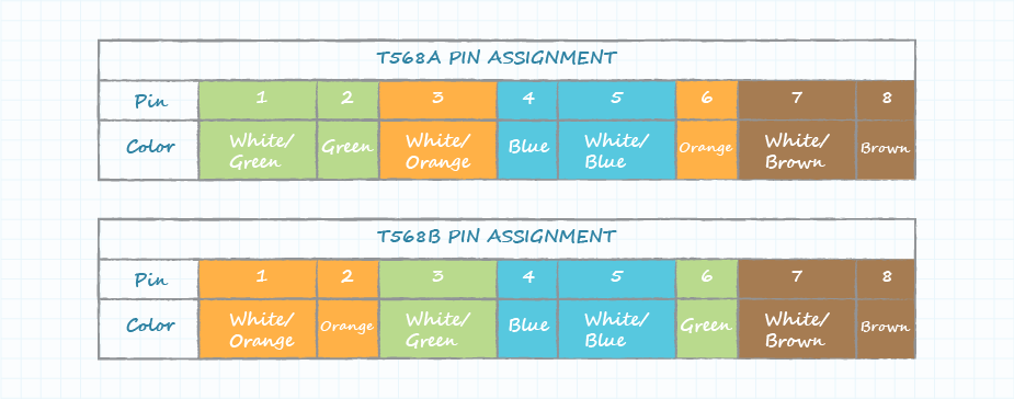
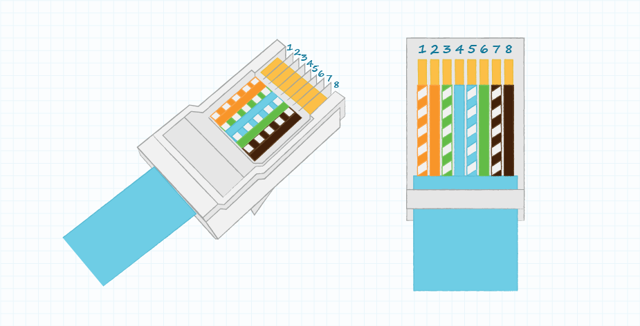
Pinout is the assignment of each of the various contacts within the connector. The color-coded wires must be inserted into the correct pinout locations in the RJ45 connector for correct functioning of an Ethernet network. For easier alignment, RJ45 pass-through connectors are available, which allow the wires to be fed through the connector and trimmed during the crimping process.
There are two RJ45 pinout standards, T568A and T568B. These define the organization of the eight wires in the connector and each has its own color scheme which must be followed. The T568A standard offers backward compatibility with older wiring. The T568B standard offers better signal isolation and noise protection. Either will work in an Ethernet network.
The type to use depends on your individual design needs and whether you are using a straight-through cable or a crossover cable. Straight-through (patch cable) has the same wiring standard at each end. Crossover cables are used to connect the same types of devices by having a T568A connection at one end and a T568B connection at the other end.
Rolled or rollover cables are flat and connect devices to a network switch console port. They are only used to establish an interface and do not transmit data.
Other terms that may be heard include Loopback, which is a connection that allows a computer to interface with itself. It is used for diagnostics, troubleshooting, and to connect with servers. Finally, a T1 is a dedicated line directly from a telecom service provider to the end user. It offers faster speeds and can carry both voice and data. While you may come across T1 lines in service, they are much less commonly used than they were 15-20 years ago.
Types of RJ45 Connectors
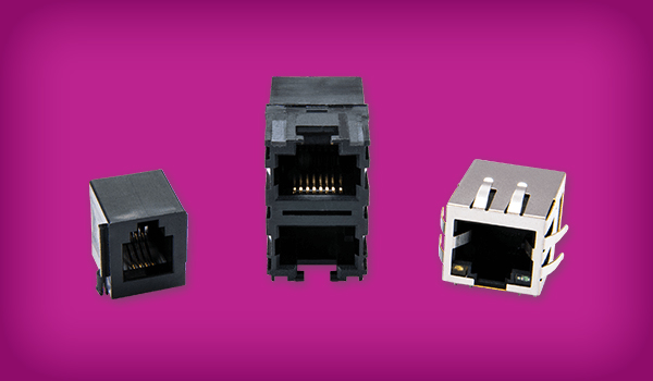
Different types of RJ45 connectors are available, depending upon the application. These include:
- Standard - 8 position, 8 connection, non-shielded.
- Shielded - internally shielded connectors that incorporate a connection to shielded cables. May also be termed RJ48.
- Ruggedized - include various external parts to protect the device from harsh environments. Also called Hi-Rel, which is short for high-reliability.
- 10 Pin RJ45 - 10 pin connector used where all serial lines are needed, as with a T1 line.
- Miniaturized - smaller footprint version of standard RJ45.
RJ45 Magnetic Jacks
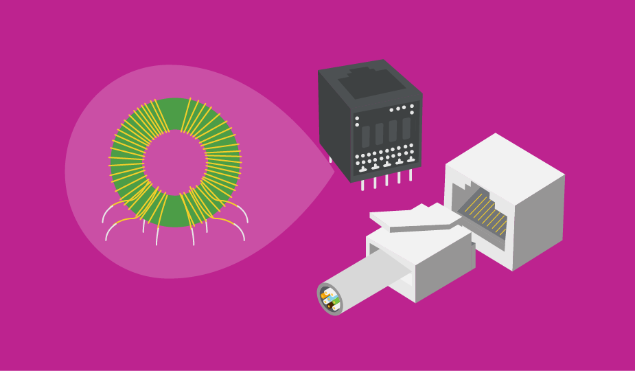
Magnetics are wire-wound components (like transformers) that provide EMI shielding, protect against faults and transients, and offer electrical isolation and signal balancing. Magnetics can be incorporated into Ethernet designs in one of two ways. The first option is to add a magnetics module to the circuit board between the PHY (Ethernet implementation) chip and the connector jack. Alternatively, an RJ45 connector with integrated magnetics in the housing can be used.
Modules tend to be cheaper than integrated devices and offer better electrostatic discharge (ESD) protection. RJ45 connectors with integrated magnetics offer better EMI shielding and more reliable connections. Both strategies have advantages and disadvantages, but magnetics must be considered if you are adding wired Ethernet into a design because they are part of the Ethernet specification for 10/100/1000 Base-T networks.
RJ45 Connector Applications
If you are designing Ethernet capability into a system, using RJ45 connectors with Cat5 or Cat6 cabling is the standard solution for connectivity in networks, peripherals, and telecommunications. The addition of features and capabilities, such as increased speed and ruggedness, to the RJ45 product line has also made this interconnection system applicable for uses beyond office or home networking.
The introduction of the EtherCAT protocol has meant expanded use on the factory floor and beyond. Some of the newer applications that use RJ45 technology include:
- Factory Automation
- Industrial Process Control
- Industrial Robotics (fabrication and assembly)
- Test and Measurement Systems
- Quality Control Systems
- Voice Over Internet Protocol (VOIP) Systems and Devices
- Internet of Things (IOT) Network Devices
Design and Product Selection Considerations
The process of product or system design always requires the asking and answering of questions. Here is a limited list of things to consider when designing products with RJ45 connectivity in mind:
- What cable lengths will be necessary?
- Will the system require shielded connectors?
- Do we use integrated magnetics or board mounted modules?
- What pinout protocol works best for the design?
- Will the product or system incorporate PoE capability?
- Do we require rugged or hi-rel devices?
- Will the product or system be subject to excessive EMI or ESD?
- What data transfer speed is required?
- What bandwidth is required?
Summary
The system of modular connectors was initially developed to improve an antiquated and labor-intensive telephone interconnect process. RJ45 connectors were introduced within this system to specifically solve the problems of interconnectivity between devices using the Ethernet protocol.
Like other modular connectors, RJ45 devices offer easy design-in, quick and easy installation, breadth of product, and user accessibility. They have been accepted worldwide for both home and office network applications and are finding increasing acceptance on the factory floor and in harsh environments.
CUI Devices offers a wide range of RJ45 connectors featuring a variety of options including integrated magnetics, PoE, LED indicators, and more.
 Tags:
Tags:
Additional Resources