How to Select a Dc Power Connector
You have finished the initial phases of your new design and are anxious to see the project through to completion, but a few tasks remain, including the selection of the low voltage dc input power connector. Specifying the proper dc power connector is not a complex task and can be completed quickly and painlessly. Selecting one of the more commonly used models is often the best choice for power supply connections as these connectors are inexpensive and readily available.
Low Voltage Dc Power Connectors
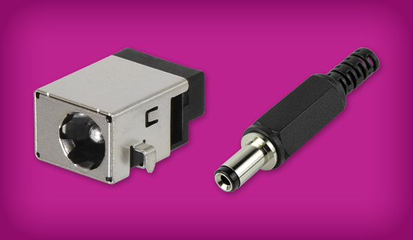
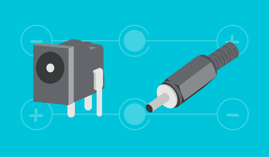
Low voltage dc power connectors, often referred to as barrel connectors, have both current and voltage ratings specified by the manufacturer. These ratings ensure reliability when using these connectors in power delivery applications. Both the jack and the plug of barrel connectors feature one exposed conductor and a second recessed conductor. A benefit of the recessed second conductor is that it is difficult to accidentally create a short between the two conductors. Additionally, there should be little concern that sensitive components will be damaged by plugging a power connector into an incorrect receptacle since barrel connectors are almost exclusively used to supply power to electronic devices.
Jacks, Plugs, and Receptacles in Dc Power Applications
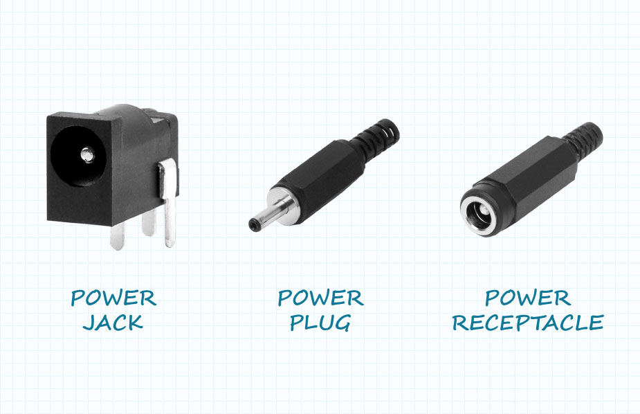
While there is not an absolute standard for the definition of barrel power connectors, the electronics industry has drifted towards common usage of the terms jack, plug and receptacle. The jack typically receives power and is mounted in the appliance, either on a PCB or in the chassis. The plug is most often located on the electrical cord and supplies power from the power supply. A receptacle is also mounted on a power cord and receives power from a mating plug.
Dc Power Connector Gender Definitions
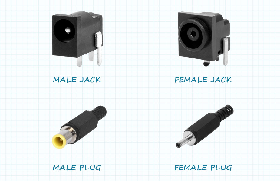
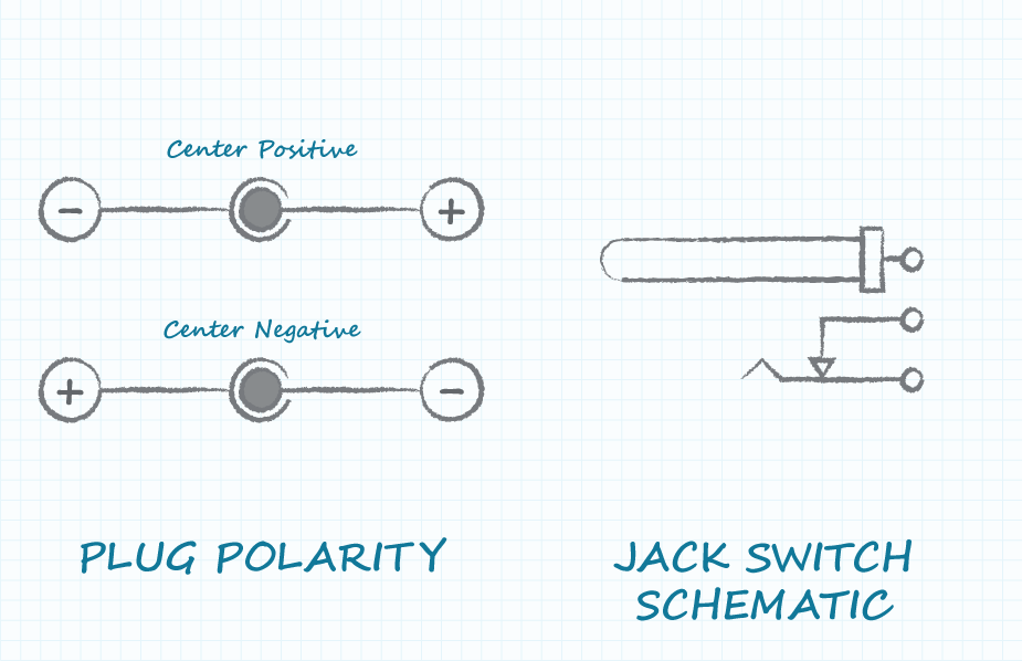
The definitions of gender for dc power connectors are less standardized than the definitions of jacks, plugs and receptacles. Some in the industry avoid declaring male and female when discussing connectors, while many engineers, following the conventions of the RF connector industry, have accepted the center pin configuration for defining the gender of barrel power connectors. The connector with the center pin is accepted as male and the mating connector is accepted as female. Users should be aware that there are standardized jack and plug combinations in which the center pin is in the jack for some and in the plug for others.
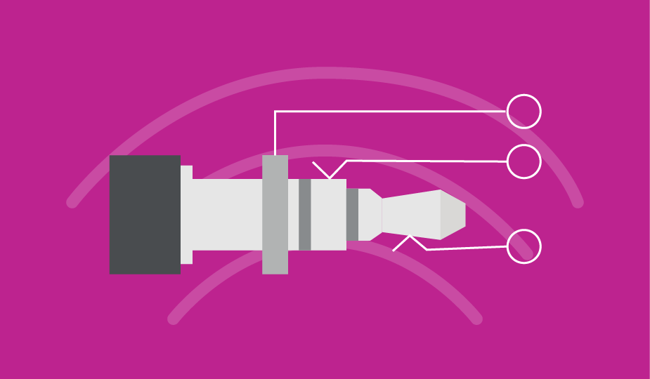
Understanding Barrel Connector Dimensions
A common standard for defining barrel connectors is the diameter of the inner pin and outer sleeve. Common diameters of the inner pin and outer sleeve are shown in the table below:
| Inner Pin Diameters (mm) | Outer Sleeve Diameters (mm) | |
|---|---|---|
| 0.50 | 2.35 | |
| 0.65 | 3.20 | |
| 0.80 | 3.30 | |
| 1.00 | 3.50 | |
| 1.30 | 4.00 | |
| 1.65 | 4.30 | |
| 2.00 | 4.75 | |
| 2.34 | 5.50 | |
| 2.50 | ||
| 3.00 |
The diameter of the inner sleeve (which interfaces with the inner pin) should be slightly larger than that of the mating pin, but manufacturers have not standardized upon a common clearance. The typical mating connection to the outer sleeve is a cantilevered flat spring and thus the clearance between the outer sleeve and the mating connector is not critical to the proper functioning of the connector.
A third dimension specified on dc power connectors is the depth of insertion. Jack insertion depth dimensions may often be less than the plug barrel lengths which can be explained for two reasons. First, the plug barrel may not be required to be completely enclosed by the receiving jack when the connectors are mated and thus a longer plug barrel length than the jack insertion depth is acceptable. Second, in some installations, the depth of the chassis wall must be considered. When the connectors are mated, that additional depth needs to be accounted for in the plug barrel length.
Conductors in Dc Power Connectors
The standard dc barrel plug or jack has two conductors, one each for power and ground. Convention is for the center pin to be power and the outer sleeve to be ground, but reversing the connections is acceptable. Some power jack models include a third conductor which forms a switch with the outer sleeve conductor. One use of the switch function is to detect or indicate the insertion of a plug. Another use of the switch function is to select between power sources dependent upon whether a plug is or is not inserted into the jack.
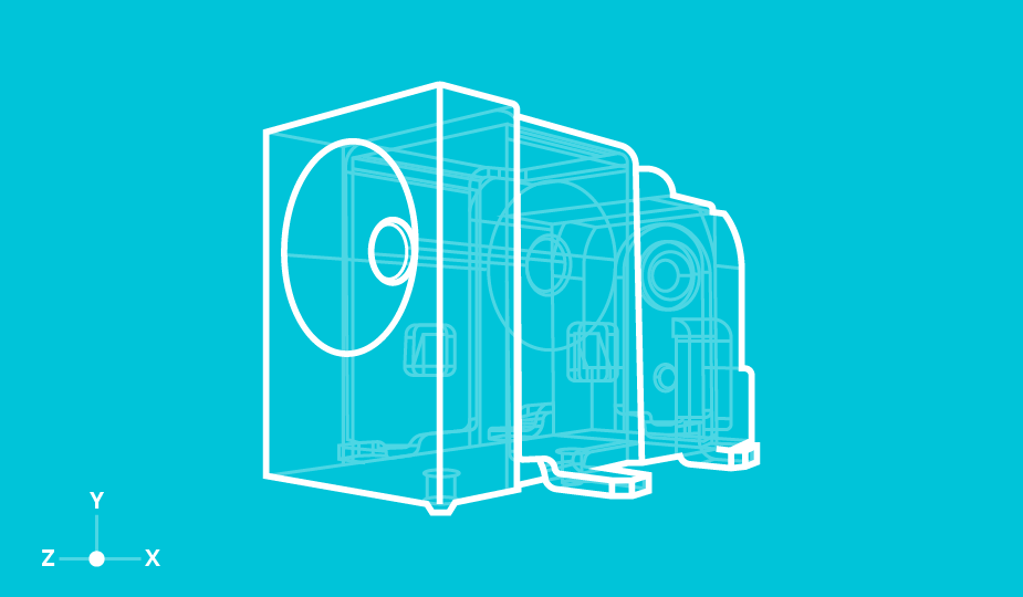
Barrel Connector Mounting Styles
In addition to selecting the connector pin and sleeve dimensions, the design engineer needs to also specify the mounting style of the dc power connector. Panel mounted connectors have the advantage of mounting almost anywhere on the product chassis, but do require wires to connect to the associated circuitry. PCB mounted connectors are available in horizontal and vertical mechanical orientations and the electrical connections can be surface mount (SMT) or through hole. It should be noted that many jacks with SMT signal connections will also have through hole pins or tabs to improve the jack’s mounting robustness. Although the tabs will be through hole soldered to the PCB, they may or may not be electrically connected to the jack. Typically mounting stabilization pins are non-conducting and are interference fit into holes in the PCB, while some horizontal jacks require an opening to be routed out of the PCB into which the jack sits. Mounting the jack within the thickness of the PCB minimizes the physical height of the jack above the PCB.
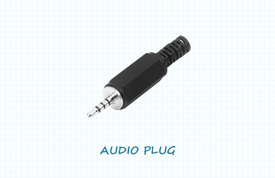
Using Audio Connectors in Power Applications
Though able to transfer a current and voltage, the use of the common audio connector (tip, ring and sleeve) is not recommended in power applications for a few key reasons. First, not all manufacturers specify this style of connector for the necessary voltage and current capabilities. A second concern is the plug (male) half of the connector is often connected to the power supply. This plug has all of its conductors exposed, which makes it easy to accidentally create a short circuit between two or more of the conductors. A third reason for not using audio connectors for a power supply is to prevent the possibility of accidentally plugging power into an audio input circuit and damaging sensitive components.
Using USB Connectors in Power Applications
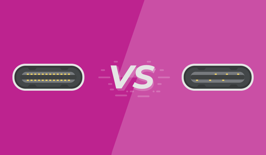
USB connectors are one of the most widely recognized and adopted connectors available to design engineers, known for both their data transfer and power delivery capabilities. However, until the introduction of the USB Type C standard, a USB connectors’ maximum power rating was somewhat limited.
With 4 power and 4 ground contacts, USB Type C connectors carry higher current ratings up to 5 A and higher voltage ratings up to 48 V, allowing for up to 240 W of power delivery. Due to their accessibility, wide adoption, and simplified design integration, USB Type C connectors have become an intriguing option for power only applications, but their high-speed data transfer specification can be cost prohibitive where charging or power is the sole function. Therefore, an emerging trend is to utilize power only USB Type C connectors where the data transfer pins have been removed, providing users with a more cost-effective solution for power only designs. For more information, read our blog post on USB Type C in power applications.
Final Considerations
The selection process for low voltage dc power connectors should be quick and painless. Design engineers can select from a wide range of dc power jack mounting styles depending upon the physical requirements of their design. Care should be taken when specifying the pin and barrel diameters and barrel lengths to ensure mechanical compatibility between the selected plugs and jacks.
 Tags:
Tags:
Additional Resources