How to Increase the Audio Output of a Piezoelectric Transducer Buzzer
How Do I Maximize the Sound of a Piezo Transducer Buzzer?
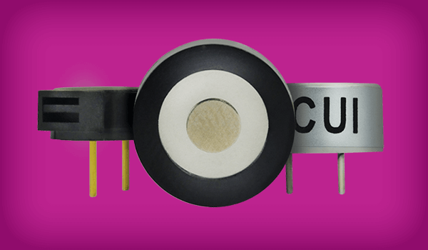
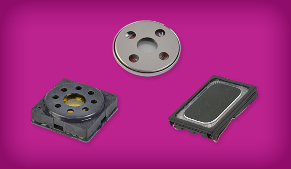
In most applications the reason for utilizing a piezoelectric transducer buzzer is to create a loud sound, where the amplitude of the sound produced by a buzzer is dependent upon both the specific buzzer selected and the signal used to drive the buzzer. There are several ways to affect the audio output of a piezo buzzer based upon the design of the driver circuit. This blog outlines the working principles of piezo transducers, common design techniques for increasing audio output, and the advantages and limitations of each. Shop CUI Devices' full range of buzzers here.
Piezoelectric Transducer Buzzer Basics
The basics of piezoelectric transducer buzzers are described in greater detail in CUI Devices’ Buzzer Basics blog post. However, as a quick refresher, a piezoelectric device is constructed of a material that physically deforms when a voltage is applied across the device. The amount of deformation and the resultant noise volume caused by the deformation are related to the voltage applied across the piezo material. It is also important to note that a transducer buzzer requires an external excitation signal, whereas an indicator buzzer, which contains an internal oscillator, only requires a supply voltage to operate.
Basic Piezo Transducer Drive Circuit
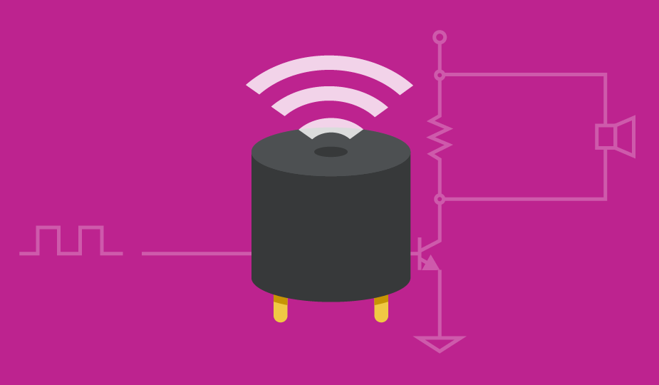
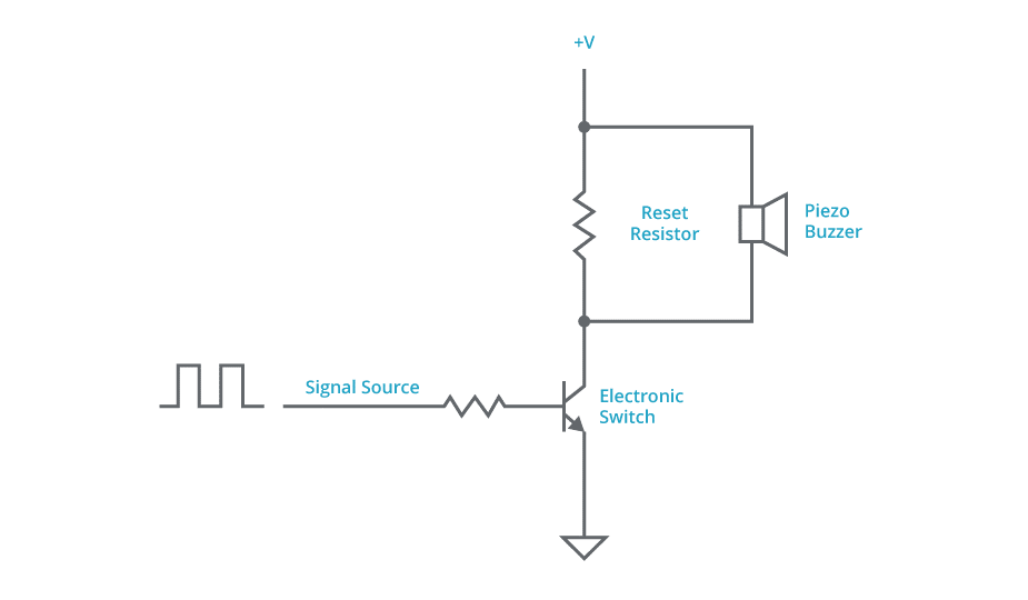
One of the most basic piezo transducer drive circuits is composed of an electronic switch, such as an FET or BJT, and a reset resistor as shown in the circuit below. The main advantage of this circuit is it only requires a few, inexpensive parts. However, it can be hampered by the fact that the voltage applied to the buzzer is limited to the supply voltage (+V) and the reset resistor dissipates power. It should be noted that the buzzer and circuit behave the same regardless of whether the one buzzer terminal is connected to the +V supply (as shown in the schematic) or to ground.
Adding Buffers to a Basic Piezo Transducer Drive Circuit
The addition of two buffer transistors, as shown in the circuit below, can reduce the power loss present in the basic driver circuit detailed previously by allowing for a higher impedance reset resistor to be used. A drawback of this circuit is that the addition of the two buffer transistors reduces the voltage applied to the buzzer by about two diode drops, or roughly 1.2 Volts. As in the basic driver circuit, the buzzer and circuit behave the same regardless of whether the one buzzer terminal is connected to the +V supply or to ground.
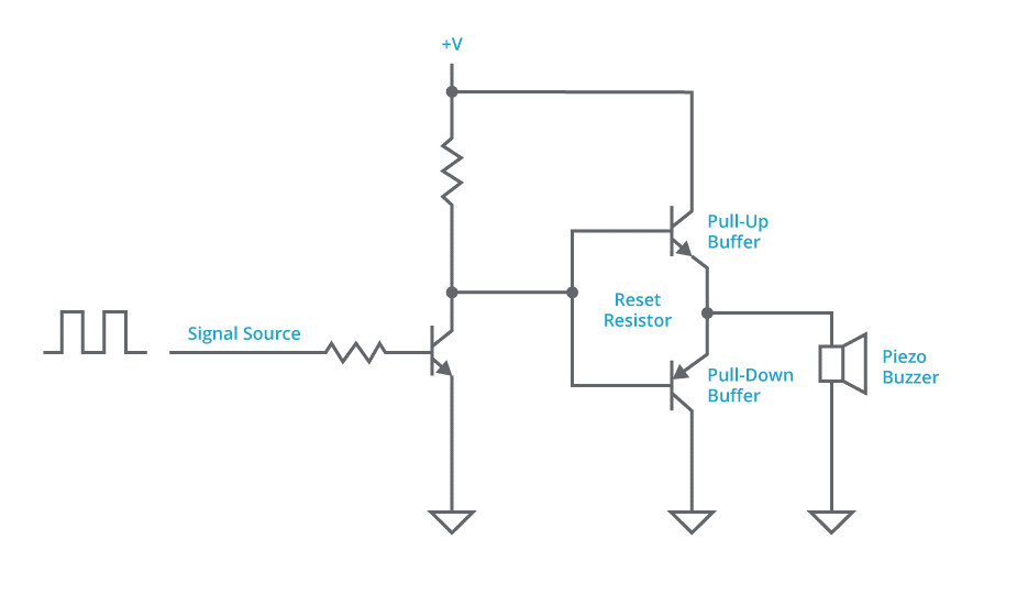
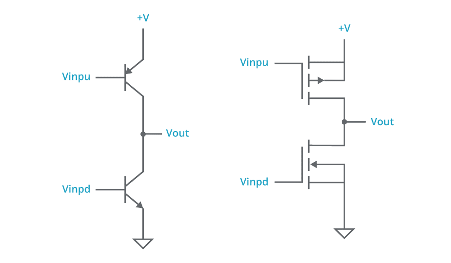
The problem of the reduced voltage applied to the buzzer can be addressed by reversing the positions of the BJT buffers in the initial buffered driver. This circuit can also be constructed with FETs instead of BJTs as the buffer components. Both buffer configurations are outlined below.
Half-Bridge and Full-Bridge Drive Circuits
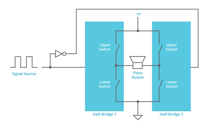
The changes to the buffer configuration mentioned in the previous section will require the drive circuit for the buffers to be more complex, which may not be desired when implementing a solution with discrete components. This form of driver with push-pull buffers is commonly referred to as a “half-bridge” driver. Two half-bridge drivers driven out of phase are known as a “full-bridge” driver and can be used with the buzzer connected between the outputs of the two half-bridge drivers. The advantage of using a full-bridge driver is that the voltage applied to the buzzer is twice the voltage as compared to a basic driver or half-bridge driver. This increased drive voltage results in a louder output sound from the buzzer while using the same supply voltage. Many versions of both half-bridge and full-bridge drivers are available as inexpensive integrated circuits and are often used to drive electric motors.
Resonant Piezo Transducer Drive Circuit
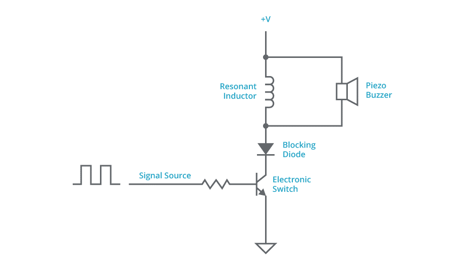
Yet another option for driving a piezo transducer is to create a circuit that utilizes the parasitic capacitance present in the transducer buzzer and a discrete inductor to form a resonant circuit. One characteristic of a resonant circuit is that energy is stored and transferred alternately between two elements. In this application the two elements that store and transfer the energy are the inductor and the parasitic capacitor. The schematic drawn below is one possible implementation of a resonant piezo transducer drive circuit. Some advantages of a resonant drive circuit are that it is simple to construct, can have high electrical efficiency, and the voltage developed across the piezo buzzer can be many times larger than the supply voltage. However, the operation of the circuit is dependent upon the parasitic capacitance of the piezo transducer, which may not be well characterized or controlled during the manufacturing process. Depending upon the desired operating frequency, the inductor could be physically large and heavy relative to the other circuit components. It can also be difficult to model the operation of the resonant circuit and thus the circuit may need to be finalized in the lab rather than at the design computer. An additional limitation is that the resonant piezo transducer drive circuit performs well at only one specific frequency, making it less suitable for applications where multiple frequency tones are required.
A more detailed discussion and analysis of the resonant driver circuit can be found in this article by EDN. It should be recognized that the circuit in the referenced article is for operation at 40 kHz. Therefore, you will need to scale the component values for operation at an audio frequency of perhaps 4 kHz.
Summary
The designer has choices and trade-offs to make regarding the selection and design of a driver for a piezoelectric transducer buzzer. Many of the trade-offs involve the cost of designing and manufacturing the drive circuit. However, once a power supply voltage has been determined, the transducer driver may be limited in the ability to enhance the output sound volume. If output sound volume is proving to be a challenge, an appropriate sound volume may be achieved by incorporating the proper drive circuit in conjunction with a buzzer with an optimal voltage rating, size, and mounting style. CUI Devices’ diverse offering of buzzers simplifies this selection process with a large range of configurations to match the specific requirements of your application.
 Tags:
Tags:
Additional Resources