An Overview of Thermal Management and Integrated Solutions
There are varying temperature thresholds that electronics can withstand, but all electronics have a lower and an upper limit before their normal operation is potentially compromised. Although extremely low temperatures can be just as harmful as extremely high temperatures, this blog will focus on high temperatures and how to mitigate them. While it is not always necessary to take additional steps to remove excess heat from an application, it should always be considered from the beginning to avoid thermal management design challenges later on. This is why understanding the fundamentals of thermal management - how heat is created, moved, and removed - is essential to creating effective thermal management solutions.
Review of Thermal Management Concepts
From a basic level, there are three methods of transferring heat: conduction, convection, and radiation. All three of these methods are utilized when cooling electronics, but their implementation and effectiveness vary greatly.
Conduction
Conduction is the transfer of thermal energy by touching objects together in which the cooler object naturally draws energy away from the hotter object. This is typically the most effective method of energy transfer as it requires the least amount of surface area to move the largest amount of energy.

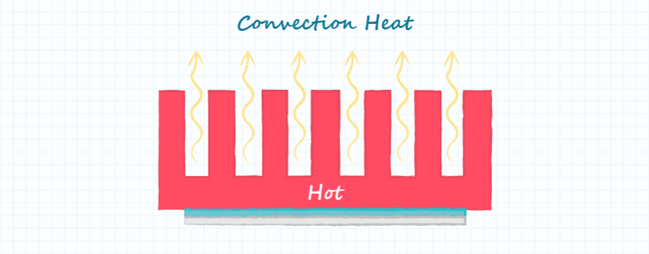
Convection
Convection is the movement of air to redistribute thermal energy. In this application, cooler air passes by the warmer device, draws some of the heat away from the device, and then carries that energy away with it. This can be passive, with only natural air currents, or forced, using a fan to speed up the air movement and therefore increase the amount of energy that can be moved. While not as effective as conduction, this method is used frequently and is nearly always the last step in a thermal management system.
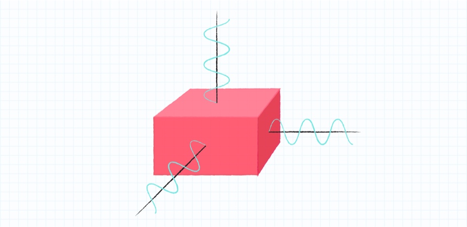
Radiation
Radiation is the emission of energy as an electromagnetic wave. The interaction and movement of charged particles in matter generate coupled electric and magnetic fields, converting the kinetic energy of heat into electromagnetic energy that propagates from the source. Radiation is typically only a factor for applications in a vacuum, where conduction and convection are not options. Comparatively radiation is very ineffective and disregarded in most thermal calculations.
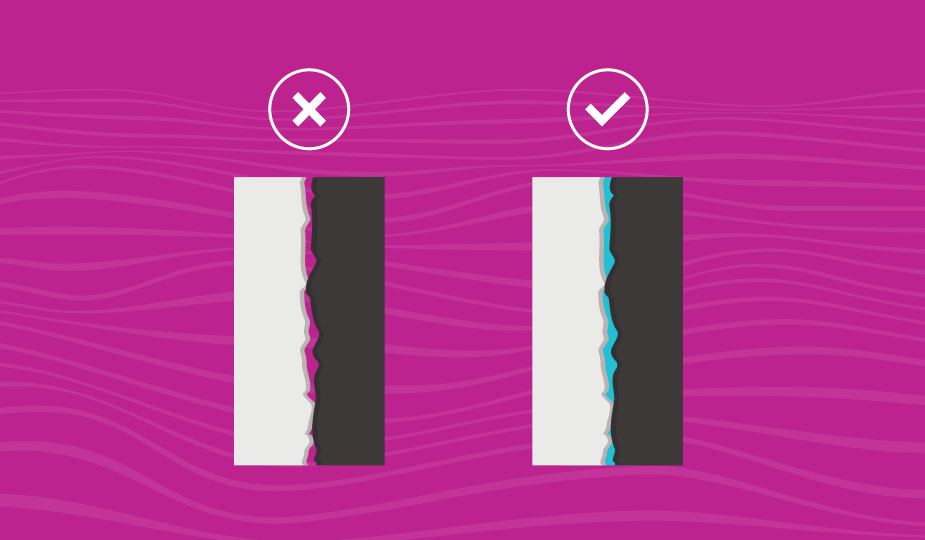
Thermal Impedance
A topic that is sometimes overlooked alongside the three basic thermal principles above is thermal resistance or thermal impedance. This factor is used to quantify the effectiveness of thermal transmission between different objects. Thermal impedance is a factor of material, shape, and size and the smaller the thermal impedance, the better it permits the transfer of thermal energy. Using thermal impedance and a given ambient temperature, it is possible to calculate exactly how much power can be dissipated before reaching certain temperatures. It is used extensively when developing thermal management solutions. Learn more in our The Importance of Thermal Interface Materials blog.
Thermal Management Options for Cooling
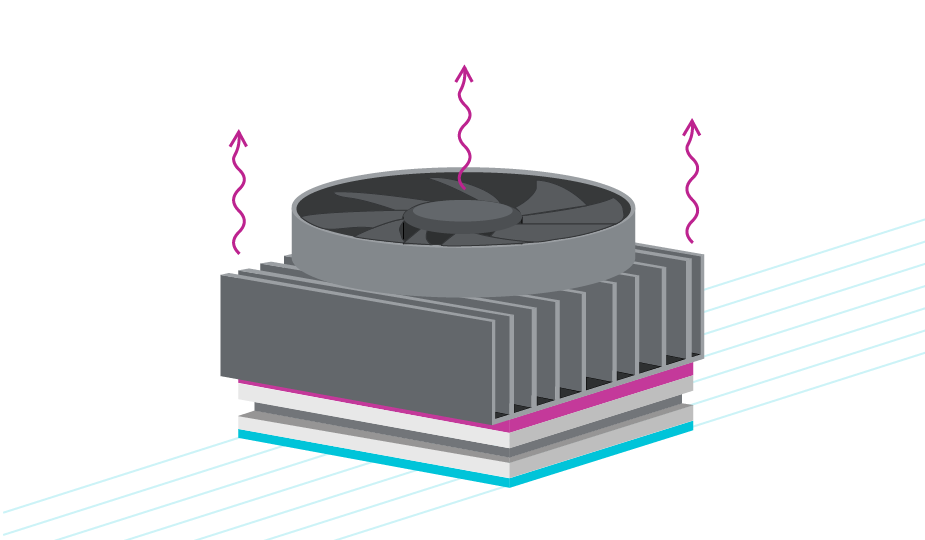
While there are many different cooling products for electronics, three types tend to rise to the top due to their efficiency and cost effectiveness: heat sinks, fans, and Peltier modules. They can all be used separately but for maximum effectiveness, they often benefit from being integrated together.
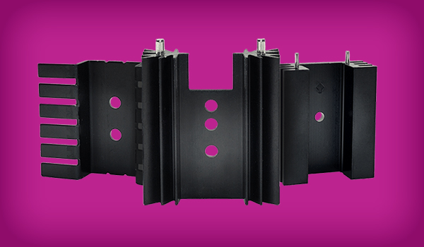
Heat Sinks
Heat sinks come in all shapes and sizes with the common benefit of decreasing the thermal resistance between the device they are attached to and air. As silent, passive components, they accomplish this by increasing the convection surface area of the device and are made of a material that transfers heat better than typical semiconductor materials. Although inexpensive with a nearly non-existent failure rate, the increased surface area usually comes at the cost of at least a marginal increase in volume due to many heat sinks being quite large. Also, while they make a significant difference, they are not as effective by themselves as other technologies, which is why they are often paired with fans to move the dissipated heat more effectively out of the application. To learn more about heat sinks, read our “How to Select a Heat Sink” blog.
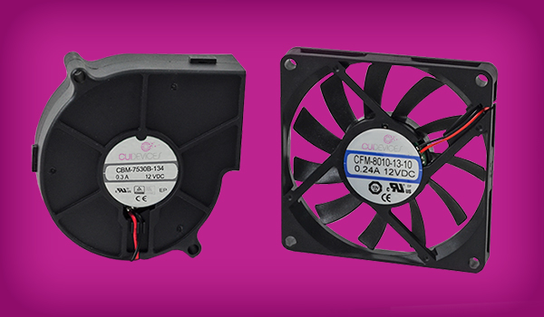
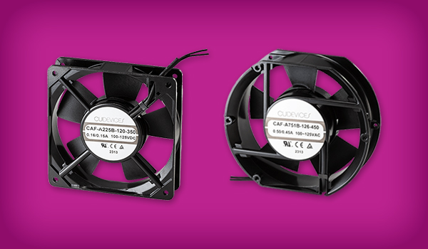
Fans or Blowers
Fans or blowers constantly move air that is in contact with a device or heat sink to eliminate pockets of warmer air that will not remove heat as efficiently as fresh, cooler air. As with heat sinks, there are a wide variety of fan shapes, sizes, and voltage levels. The shapes and sizes are related to airflow, typically measured in Cubic Feet per Minute (CFM). Depending on the design needs, certain fans further offer speed control that can be used in feedback systems to actively moderate the CFM. While fans reduce the size of heat sink needed and are relatively inexpensive, they are active devices that require power, have moving parts, are more prone to failure, and can be quite noisy. Shop CUI Devices' full range of ac fans and dc fans.
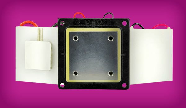
Peltier Devices
Finally, Peltier devices are semiconductor components that use the Peltier effect to transfer heat from one side of a module to another. In cooling applications, the cool side is attached to the device and it actively moves heat from the cold side to the hot side of the Peltier module. This active movement of energy also requires power, which actually adds heat to the overall system, making them best coupled with heat sinks and fans. Peltier modules are an intriguing thermal management component because they can be actively controlled with precise temperature regulation and can even bring devices below the ambient temperature, unlike the other options by themselves. As these are cooled via semiconductor principles, there are no moving parts to fail, making them flexible and robust. However, adding a Peltier module increases the expense of the cooling system, adds heat to the overall application, and uses more power than a fan or a heat sink alone. Thus, the addition of a Peltier module is not ideal for every application but can still be extremely useful in more demanding situations. Our “How to Select a Peltier Module” blog provides more background on this subject.
When approaching a project, if it is established that a thermal management plan needs to be created, the pros and cons between each of these cooling products should be reviewed. Taking into consideration cost, size, reliability, and power consumption, the designer can decide which aspects are most important in each particular project.
Thermal Calculation Example
To show how an integrated thermal solution can easily be created, presented is a hypothetical problem and solution:
Assume there is a device in a 10 mm x 15 mm package that generates 3.3 W of heat in a steady state. This device is used in an environment where the ambient temperature is 50°C, but its ideal operational temperature is 40°C. However, no part of the system should ever exceed 80°C.
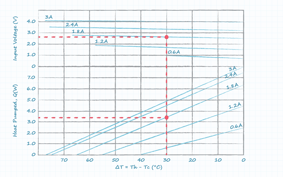
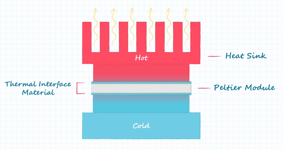
To solve this problem, a Peltier device will be needed to cool the device below the ambient temperature. Ideal for this device, CUI Devices’ CP30138H module can remove 3.3 W of heat. The Peltier module will be attached to the device using a Thermal Interface Material (TIM), SF600G in this case. Importantly, the graph on the CP30138H datasheet shows that the Peltier module requires 1.8 A at 2.6 V to achieve the 3.3 W of heat transfer with a temperature differential of 30°C, meaning that the Peltier module itself will create an additional 4.7 W of heat.
To remove these 8 watts more efficiently from the Peltier module, the HSB28-606022 heat sink will be attached using the SF600G TIM. With an area of 8.8 mm x 8.8 mm, the TIM has a thermal resistance of 1.076 C/W (rounded to 1.08 in the calculations). On the other hand, the heat sink, assuming 400 LFM of airflow is moving across it, has a thermal resistance of 0.9 C/W, bringing the total thermal resistance to 1.98 C/W. In this scenario, to provide consistent airflow of 400 LFM, a fan from the CFM-40BG series could be used. To make it easier to convert the CFM rating to the LFM rating that is needed, CUI Devices has an online airflow conversion calculator available for general use.
To restate, this solution will have the device producing heat connected via a TIM to a Peltier module, which is in turn connected to a heat sink via a TIM, all of which is being cooled with 400 LFM of 50°C air.
With these various data points in mind, the temperature of the device at steady state can be calculated. The Peltier module will maintain its cool side at around 36°C - at the cost of creating an additional 4.7 W. The heat sink will now need to dissipate 8 W of heat in a 50°C ambient temperature environment, with a total thermal resistance between the Peltier module and ambient air of 1.98 C/W. The final step is to multiply 8 W times 1.98 C/W, which finds the increase of temperature over ambient. In this case, the heat sink will reach 15.84°C, or 65.84°C total, well under the 80°C requirement. Thus, this solution effectively addresses the thermal management needs of the system.
Conclusion
While thermal management products will not always be necessary, heat is an almost inescapable fact that will need to be managed in many applications. For example, integrated thermal solutions are found in a wide variety of consumer applications including refrigeration, HVAC, 3D printing, and dehumidifiers. Alternatively, these solutions can be found in scientific and industrial applications such as thermal cyclers for DNA synthesis as well as lasers to avoid laser wavelength drifting. By understanding how heat sinks, fans, and Peltier modules work, these applications and more can be made to work longer and more effectively by keeping them within their thermal design limits.

 Tags:
Tags:
Additional Resources