How to Select a Peltier Module

Common thermal management solutions used in electronics applications address cooling objects with heat exchangers and fluid flow. The heat exchanger is typically either the electronic package itself or an extruded or stamped heat sink attached to the package. Air is the most common fluid used in thermal solutions, either with natural convection or propelled by a fan. In most of these solutions the temperature of the object being cooled remains above the ambient temperature. Peltier modules are electronic devices designed for cooling objects to below the ambient temperature or maintaining objects at a specific temperature by controlled heating or cooling. Selecting or specifying a Peltier module is not difficult but a basic understanding of module characteristics can be helpful to ensure the process flows smoothly.
The Thermal Problem to be Solved
Many electronic components provide an improved signal to noise ratio at cooler temperatures or are susceptible to damage when operating at temperatures exceeding specifications. Similarly, some chemical reactions must be maintained at or below a specific temperature. In these applications a Peltier module can be used to solve thermal issues and cool objects to below the ambient temperature where a conventional heat sink and fan cannot do so. Additionally, Peltier modules and the appropriate control circuit enable the ability to maintain an object at a specific temperature even under rapidly fluctuating thermal loads.
Peltier Module Basics
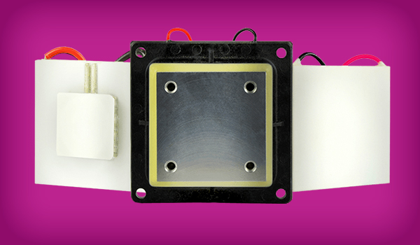
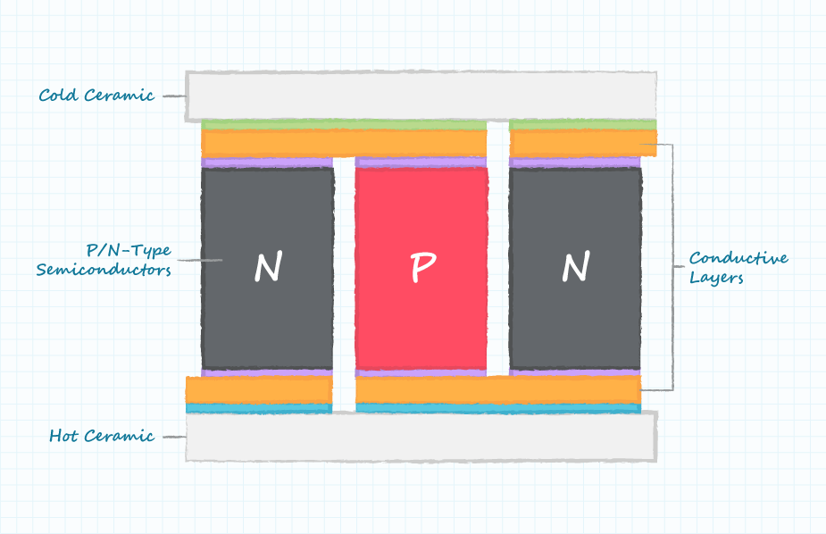
Peltier modules contain two external ceramic plates separated by semiconductor pellets. One of the plates absorbs heat (becomes cooler) and the other plate dissipates heat (becomes hotter) when a current is passed through the semiconductor pellets. More details regarding the construction and operation of Peltier modules can be found in this blog.
The following constraints should be understood when selecting or specifying a Peltier module, which we will cover in the following sections:
Heat Transfer Through Peltier Modules
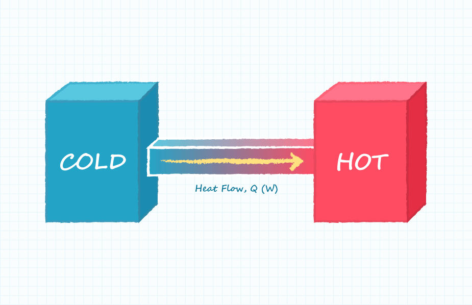
The amount of heat to be transferred through a Peltier module from the cold side to the hot side is denoted Q and is specified in Watts. This parameter may be the heat generated by an object to be cooled or it may be the heat conducted to the ambient environment from the object being cooled. It should be understood that Peltier modules do not possess the ability to absorb thermal energy. Peltier modules only transfer thermal energy and the energy being transferred will need to be dissipated on the hot side of the module.
Temperature Difference Across Peltier Modules
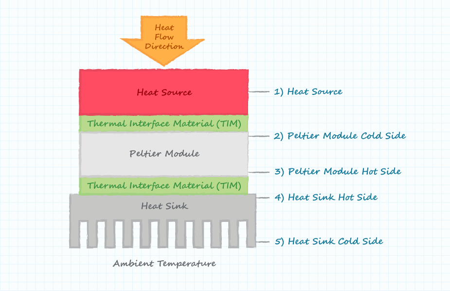
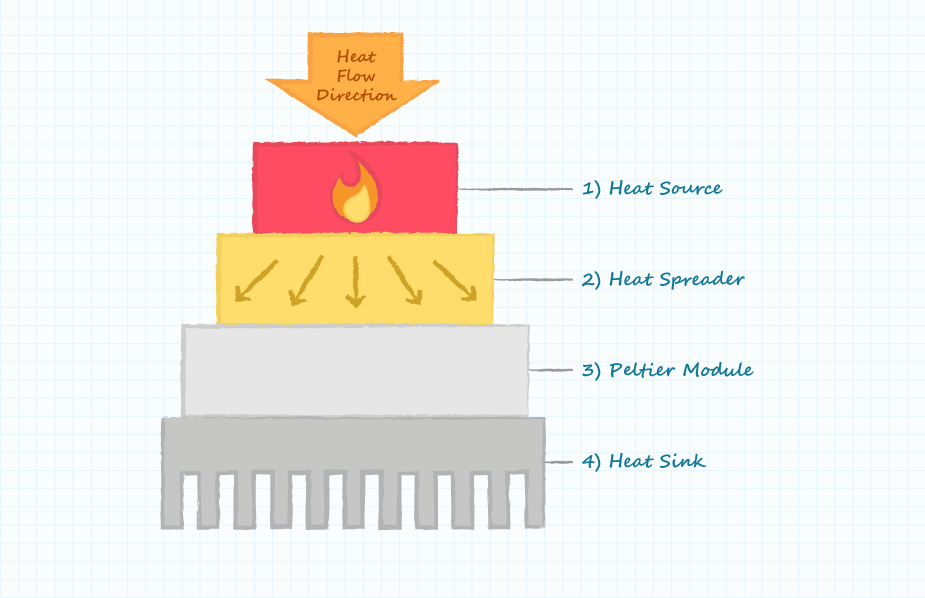
The temperature difference specified in a Peltier module datasheet (ΔT) is measured on the outside surfaces of the two ceramic plates of the module. Care must be taken to understand if there is any temperature difference between the Peltier module plates and the external system temperatures of interest. The following diagram indicates five potentially different temperature regions of a Peltier module system.
Temperature of the Hot Side of Peltier Modules
The characteristics of Peltier modules also change with operating temperature. Some vendors, such as CUI Devices, provide specification data for more than one operating temperature. Specification data will probably not be available for the specific operating temperatures of the application and thus the closest available data should be used.
Surface Area of Peltier Modules
The surface area of Peltier modules is typically specified based upon either the area of the object to be cooled or the area available for heat dissipation. An area mismatch between the area available and the area of the Peltier module can be compensated for by the use of a low thermal impedance heat spreader. A simple heat spreader can be manufactured from aluminum or copper.
Required Operating Current
Peltier modules are current-driven devices similar to LEDs. The desired operating parameters are most conveniently achieved by driving the module with a controlled current source and allowing the current source to provide the required load voltage (the voltage compliance of the current source). This is analogous to providing a specific voltage to a voltage driven device and then letting the voltage source provide the required current (i.e. providing a voltage to a microprocessor and ensuring the voltage source can provide the required load current).
Peltier modules can be driven with voltage sources but doing so will make it more difficult to accurately control the heat flow and temperature difference across the module.
Required Operating Voltage
The required voltage compliance of the current source will be determined from the Peltier module datasheet and operating constraints. Maximum current (Imax) and maximum voltage (Vmax) are operating limits, not the module's absolute maximum rated values. Recommended operation is only up to 70% of these limits because operation beyond limits will result in decreased heat absorption and efficiency as Joule heating increases.
An Example of Specifying the Proper Peltier Module
The following example demonstrates the process of selecting or specifying a Peltier module for an application. In this example we will be using the CP603315H Peltier module.
Conditions
- Heat transfer through the module: 20 W
- Temperature difference across the module: 20°C
- Temperature of hot side of module: 30°C (use 27°C graphs)
- Surface area of object: 30 x 30 mm
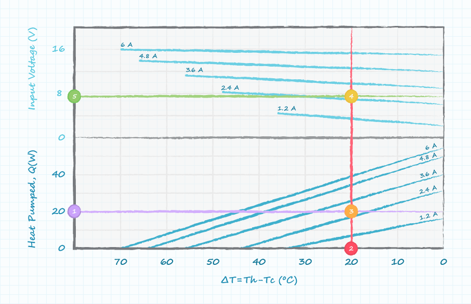
- Draw horizontal line at 20 W on lower vertical axis which represents the power transferred through the Peltier module.
- Draw vertical line at 20°C on lower horizontal axis which represents the temperature difference maintained across the Peltier module.
- Operating current of 2.7 A is interpolated from where horizontal line (1) and vertical line (2) intersect. This is the current required to operate the Peltier module.
- In the upper half of the graph mark where vertical line (2) intersects 2.7 A.
- Operating voltage of 7.5 V is interpolated from drawing a horizontal line from the intersection in step 4 to the upper vertical axis. This is the required voltage compliance of the current source.
Example Summary
- Peltier module selected: CP603315H
- Heat transferred through Peltier module: Q = 20 W
- Temperature maintained across Peltier module: ΔT = 20°C
- Temperature of Peltier module hot side: Th = 30°C
- Current source required to power Peltier module: I = 2.7 A
- Required Voltage compliance of current source: V = 7.5 V
- Power dissipated in heat sink in addition to that transferred through Peltier module: P = 20 W
- Total heat to be dissipated by heat sink: 40 W; 20 W heat transferred plus 20 W electrical power
Conclusion
Peltier modules can be an optimum solution when there is a need to cool an object to below the ambient temperature or to maintain an object at a specific temperature. To ensure a successful design it is important to select a vendor with multiple choices of Peltier modules and adequate characterization data. In addition to partnering with a reliable vendor it is also critical to understand the subtle details regarding module implementation and operation such as the basics outlined in this post.

 Tags:
Tags:
Additional Resources