What You Need to Know About Relays
If you have ever cranked-up your home furnace, used a building elevator, or turned on your TV with a remote control, you have set a relay into action. Relays provide an indispensable function in thousands of consumer, commercial, and industrial products and systems. First developed in 1835 for long distance telegraph circuits and later in telephone exchanges, they still work reliably, quietly, and efficiently.
What Are Relays?
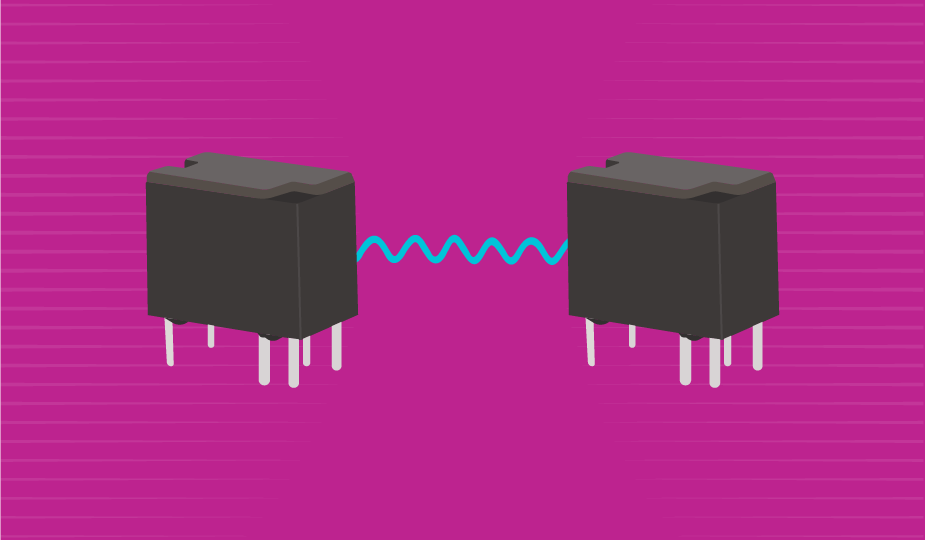
In a very practical sense, relays are simply electrical switches. They use a low-power signal to control a high-power circuit, which may be close-by or at a distance. Their design enables the low power signal to be effectively isolated from the high-power circuit (also known as galvanic isolation), enabling safe and robust electrical operation for the user. They can be used to control a single circuit or multiple circuits and can act as amplifiers or circuit breakers. The control of device power from a distance also means additional safety for industrial processes that may pose a physical hazard to operators. Available in a wide variety of packages, current capacities, mounting options, and footprints, they are as ubiquitous as the common switch.
How Relays Work
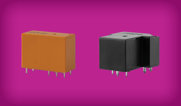
To help make sense of the subject, we first need to categorize relays. They come in two basic types: electromechanical (EMR) and solid state (SSR), the difference obviously being those with moving parts versus those with no moving parts.
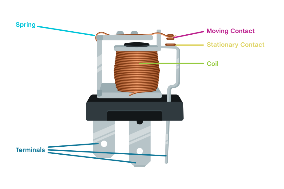
The electromechanical version has been around the longest, and contains contacts, an armature, a spring, and an electromagnet. In their most simple operation, a spring holds the armature in place. When a current is applied, the electromagnet attracts the armature whose movement closes a set of contacts and allows current to flow to the circuit.
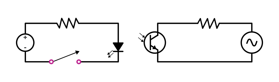
Solid-state relays, which first appeared in the late 1950’s, perform the same basic function as electromechanical relays, but they are completely electronic and have no moving parts. They employ an input circuit, a control circuit, and an output circuit to control current. When a voltage higher than the specified pickup voltage is applied, the control circuit activates the relay. When the voltage drops below the dropout voltage, the relay is deactivated.
Electromechanical vs Solid-State Relays
Both electromechanical and solid-state relays are reliable devices, but they each have pros and cons which should be considered early in the design stage for your final product or system.
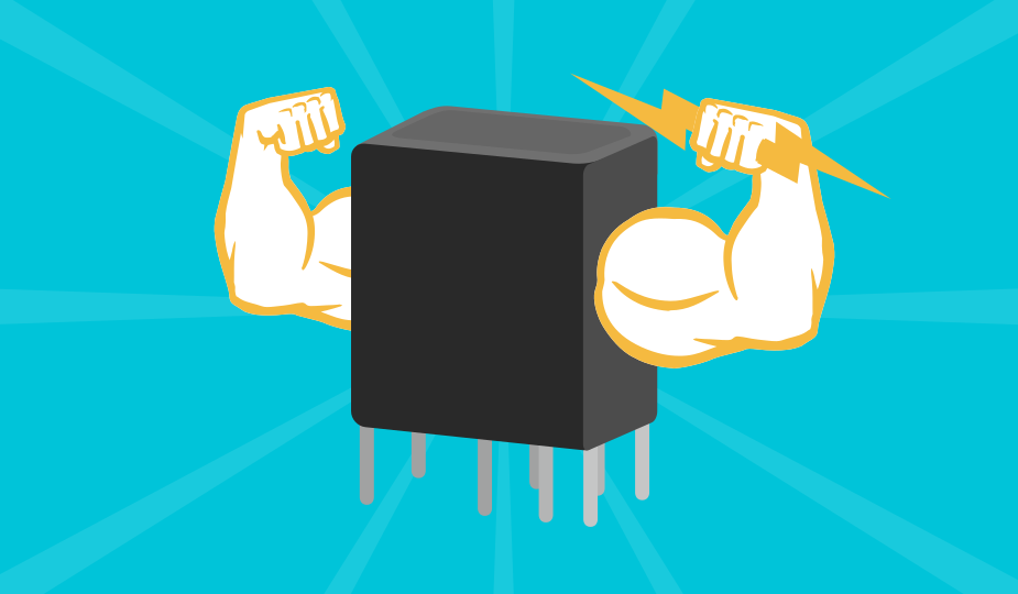
Electromechanical relays are robust devices with simple operation that perform reliably in a variety of applications that can include high current and hazardous operating environments. As this design is nearly two centuries old, their performance characteristics and operational fundamentals are well known. They offer complete electrical isolation, can tolerate high current and voltage transients, and are insensitive to electrical noise (EMI/RFI).
The basic design of electromechanical relays, however, can lead to physical degradation over time. They can also be subject to contact arcing resulting in pitting and shorting. The contacts can also be affected by corrosion and oxidation. Due to their mechanical nature, they can also be subject to contact bounce from shock and vibration, can generate their own EMI/RFI noise, and may be affected by external magnetic fields.
Solid-state relays, due to their design with no moving parts, offer longer life than electromechanical relays and operate with a much lower control power. They also provide quicker on/off cycling, no arcing, and no contact bounce. They are also not affected by external mechanical shock, vibration, or magnetic fields. Solid-state relays also operate in a much lower voltage range than electromechanical, which makes them applicable for electronic devices but not for devices with higher power demands.
Due to their unique design, solid-state relays may also be susceptible to voltage or current transients and to EMI/RFI noise. Solid-state relays also may generate more heat than their mechanical cousins and may be affected by ambient temperatures. Finally, complete electrical isolation between the control signal and the load is not possible with normal semiconductor switches, but can be achieved through the use of photo-coupled devices, which use optoelectronic components to isolate the input and output.
Typical Uses of Relays
In a broad sense, relays are used in any application requiring the safe control of a large current by a smaller one. They are commonly used where it is impossible to have a direct connection between the control circuit and the load due to operator or equipment risk. In an application that uses a lot of power, relays can be used with a single, less expensive, low power wire to control current flow at a distance.
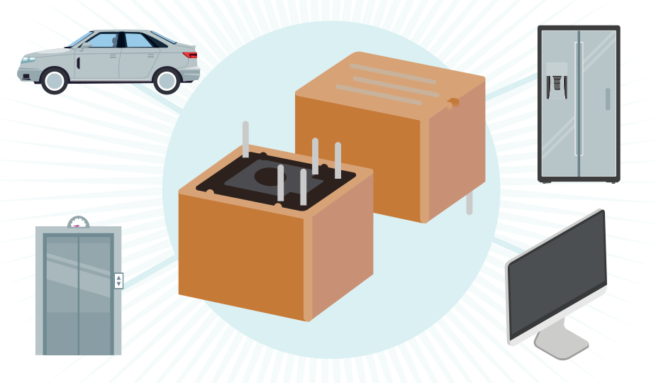
Given their simplicity of design and reliable operation, relays are used in devices and systems across a wide range of industries and markets. Since the advent of the relay, they have been used in transportation and automotive type applications, as well as electric power systems, medical, aerospace, defense, and consumer electronics. Later, as HVAC was developed and became mainstream, they became instrumental in residential, commercial, and industrial HVAC systems. More recently, they have been used in the electrical vehicle aspect of automotive, alternative energy, and datacom or telecom areas. From this list, it is easy to see that relays truly are ubiquitous. Suffice to say that many systems and devices would be less than effective or even non-functional without the ability to safely control power that is provided by the common relay.
Common Types of Relays
The many different types of relays available each attempt to address specific application needs. Be aware that manufacturers may have slightly different terms for their individual product offerings. If you have questions, it is best to reach out to the supplier or your authorized distributor for answers. Here is a short list of the major types available:
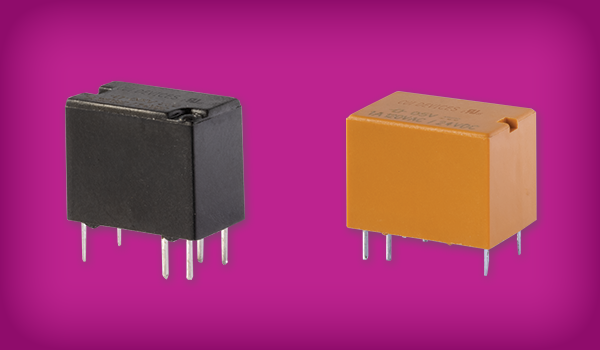
- General Purpose: common electromechanical relays that use ac or dc current of 12 to 230 V and control from 2 to 30 amps.
- Signal: relays used to control low power loads usually less than 2A. Learn more in our blog post, An Introduction to Signal Relays.
- Power: relays designed to control high power loads, offering less heat generation and reduced arcing. Learn more in our blog post, An Introduction to Power Relays.
- Machine Control: heavy duty, durable relays for use with large industrial applications.
- Latching: relays that maintain their set or reset condition (either ON or OFF) until they receive an inverting voltage signal.
- Reed: compact and fast operating relays that use an electromagnet to control one or more hermetically sealed reed switches, offering immunity to outside contaminants or moisture.
- Zero Switching: relays that turn the load on when the control voltage is applied and the load voltage is close to zero, and then turn the load off when the control voltage is removed.
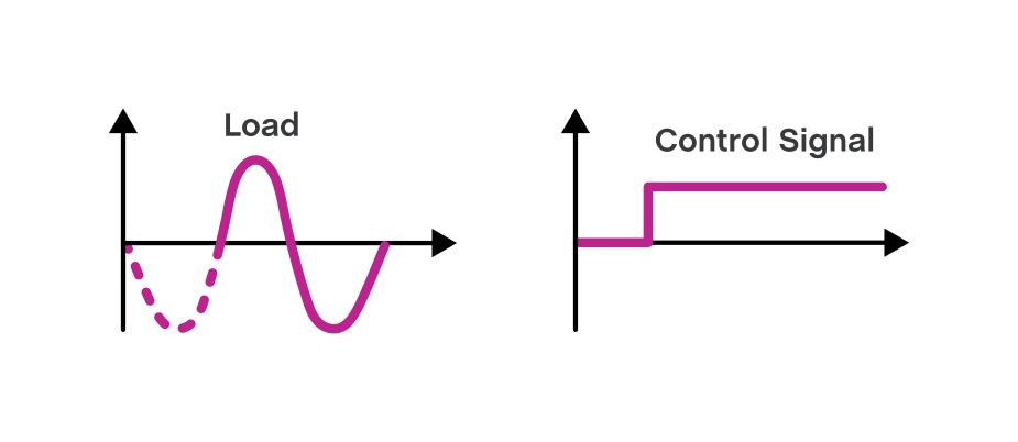
- Peak Switching: relays that turn the load on when a control voltage is applied and the load voltage is at its peak, then turn the load off when the control voltage is removed and the current load is close to zero.
- Instant ON: relays that turn the load on immediately when the pickup voltage is applied
- Time Delay: control relays with a built-in timer in order to control events based on time.
- Analog switching: relays that control the output voltage as a function of the input voltage, allowing for infinite output voltages within the rating of the relay.
- Optically coupled: solid-state relays that offer isolation between the control and power circuits by switching in response to an internal light source.
- Military/Hi-Rel: relays specifically designed to operate in harsh environments.
Also, relays can be either normally open (NO), when the contacts are open and the circuit is not energized, or it can be normally closed (NC), when the contacts are closed and the circuit is not energized. In short, relays are usually specified as either NO or NC when no power is applied.
Relay Ratings and Configurations
Relays are rated based on the amount of power that can be safely switched through the device. Ratings are either ac or dc and usually expressed in amperes. The rating of a relay must be as large or larger than the device it will be controlling.
Since relays can control multiple circuits simultaneously, they come with configuration designations to identify their characteristics. These designations are:
- SPST - single pole, single throw
- DPDT - double pole, double throw
- 3PDT - three pole, double throw
- SP3T - single pole, three throw
In addition to the amount of poles and throws that a relay may have, another shorthand way to describe important aspects of relays is using the term “forms.” Reading phrases such as “1 Form A” or “2 Form C,” you can ascertain two important pieces of information quickly. The type of form indicates if the switch is normally open or normally closed, and in the case of SPDT switches, whether they are break-before-make or make-before-break. In addition to that, the 1 or 2 before form tells you how many of those style contacts are available in the relay. A few of the more common styles are:
- Form A - normally open
- Form B - normally closed
- Form C - break-before-make SPDT switches
- Form D - make-before-break SPDT switches
Relay Selection Steps and Questions to Ask
Selection of the proper relay for your design requires information about product or system needs today, and anticipated needs tomorrow. There are some basic facts, however, that you will need to know before you can specify the relay you need.
- What is the maximum voltage ac or dc that needs to be switched (load voltage rating)?
- What is the maximum load current, including potential surges (load current rating)?
- What is the voltage range of the control current and is it ac or dc?
- What mounting style do you require - PCB, plug-in, DIN rail, or panel mounted?
- What is the number of circuits to be switched?
- What load type do you require (inductive or resistive)?
- Do you require a thermal management solution for resistive heat build-up?
As you work your way through these questions, there are the physical non-ideals that should be factored into the real-life performance and requirements of the relays themselves. Make certain to take these items into consideration as you answer the questions above.
- Input power surges – if the individual relay is not specified properly, surges can destroy the device and threaten your system.
- Contact bounce – this tendency of electromechanical relays can not only degrade the contacts over time, but can also produce EMI/RFI that can affect your system.
- Arcing – this electrical discharge across the contact gap will degrade the contacts, produce noise, and may be dangerous in a hazardous environment.
- Environmental factors – relays are robust, but performance characteristics may be affected by environmental vibration, heat, humidity, and magnetic fields.
Summary
For a product that has been around for many years, the basic relay is used in tens of thousands of devices and systems across consumer, industrial, and defense markets. Although they began as simple components in telegraph systems and even used in the development of the first computers, today they continue to provide the basic function of safely and efficiently controlling electrically powered devices from a distance. To address your low-level or high-level current switching needs, CUI Devices has you covered with a range of power and signal relays rated from 2 up to 40 A.
 Tags:
Tags:
Additional Resources