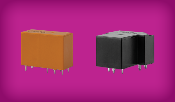
An Introduction to Power Relays
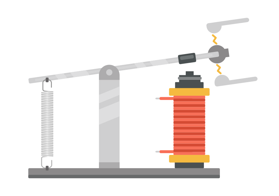
As noted in several of our other technical blogs on this subject, relays are basically switches that control other switches. They use a low-power signal to control a higher-power circuit. Initiating the low power signal energizes an electromagnet which moves an armature and causes electrical contacts to close, sending power to the controlled circuit.
This design effectively isolates the low-power signal from the higher-power circuit, protecting the operator from harm and equipment from damage. It also allows for the control of a device or system from a distance. Electromechanical relays have been around since 1835, and even though their components and variety have gotten more sophisticated and refined over the years, their basic function remains the same.
What Are Power Relays?
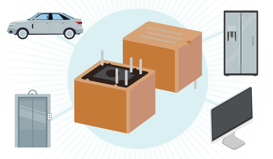
All electrical relays control power, but not all relays are correctly termed “power relays.” To be more precise, power relays are products specifically designed to handle high-level current switching, from several amps to much higher amounts. The built-in capacity of power relay contacts to handle larger currents, coupled with their larger size and more robust coils makes power relays a good choice when switching currents of generally more than 10 amps. Some usage examples include automotive systems, elevators, valve actuators, or devices with high initial current surges, like motors, solenoids, power supplies, or electronic ballasts.
Contact Arcing and Power Relay Benefits
Like most other electrical components, all relays have some limitations in terms of the power they can safely handle. Each model has a maximum power rating for the power that can be controlled, allowing them to be efficiently matched with low-power loads like light bulbs, to high-power loads like large motors. If the power rating of the relay is exceeded, however, permanent damage to the relay will likely happen.
If the contacts are not perfectly aligned, this can also lead to contact arcing in the relay, which is the flow of current through the air gap between contacts in the relay when they are open but near each other. The danger from sparks and heat are not the only negative effect of arcing. Arcing can also damage the relay by eroding the contacts and damage nearby equipment by generating unwanted electrical interference.
This issue is solved using power relays, which are typically employed to handle the electrical loads of high-current devices like heaters, motors, lighting arrays, and other industrial equipment. The higher current and voltage ratings of power relays are enabled largely through the use of switch contact materials that are significantly different from regular relays.
A Word About Relay Contact Materials
Current flow through the contacts of a relay is met with resistance, which depends on the size of, and the material used in the contacts. Increasing the resistance increases the power consumed within the relay itself and the heat generated. One of the ways to lower contact resistance is through the selection of the material from which they are made.
Regular relays typically use silver nickel contacts. This metal has been used in relays since their introduction and is typically good for switching resistive loads (simple loads where the current and voltage are in phase with each other).
Relays rated for higher loads (power relays) use contacts made from silver cadmium oxide, silver tin oxide, or a gold alloy and are good for switching inductive loads (current and voltage are out of sync with each other, sometimes causing large spikes in current or voltage). Both of these contact materials offer less electrical resistance and reduced contact welding from high in-rush currents. The use of silver tin oxide avoids the environmental concerns of alloys using cadmium, which is regulated by some countries.
Power Relays vs. Signal Relays
Power relays and signal relays are the two most popular variants of a general relay and can benefit from a more direct comparison. Importantly, power relays expect fewer lifetime cycles yet are much more concerned with higher voltages and currents. Signal relays expect a higher lifetime cycle count but deal with lower voltages and minimal amounts of current. These differences in usage require significantly different approaches in their construction. Due to this difference in construction, while power relays are an excellent choice for switching high-power devices, they are not a good match for use with low-power devices. The characteristics of the contact materials used in power relays are not ideal for low-power switching. This is because the lower the voltage being switched, the more critical the physical connection between contacts, which is controlled by contact pressure and cleanliness of the contacts and not the material used. More obviously, a signal relay that is used for a power application will most likely fail catastrophically due to overvoltage or overcurrent. Even if it survives, it will lack important features such as arc prevention and contact self-cleaning. When it comes to choosing between the two types, the most important guideline to follow is to always match the power level being switched with the power rating of the relay. You can read about signal relays for low-power devices in our blog post titled, An Introduction to Signal Relays.
Types of Power Relays
As with regular relays, power relays come in two basic types, electromechanical and solid-state. Electromechanical power relays use electrical coils, magnetic fields, springs, movable armatures, and contacts to control power to a device.
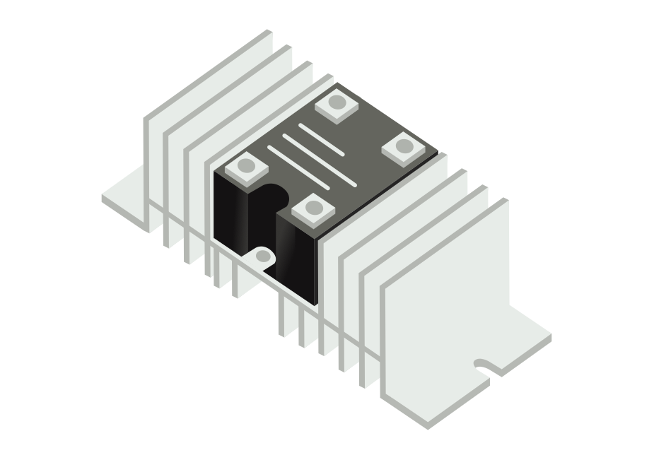
Solid-state relays for high power applications switch both ac or dc currents using no moving parts. They instead use a semiconductor, such as a silicon-controlled rectifier (SCR), TRIAC (triode for alternating current), or switching transistor to switch current. While solid-state relays are used to switch high-power loads, the cost/benefit calculation erodes as the power demand increases due to the increasing costs of appropriate power semiconductors and the necessity of additional thermal management components.
Power Relay Configurations and Ratings
Like regular relays, power relays are classified by contact configuration or description, designating the number of devices they can control simultaneously. The most common classifications are:
- SPST – single pole, single throw
- DPDT – double pole, double throw
- 3PDT – three pole, double throw
- SP3T – single pole, three throw
Relay contacts are listed either as normally open (NO) or normally closed (NC) depending on what state they are in when no power is applied to the relay.
Relay ratings refer to the amount of power that can safely and efficiently be switched by the relay. This rating is usually expressed as either ac or dc, or both, and given in terms of amperes. The rating level of a relay must be as large as the rating of the device being switched with a safety factor included.
Exactly like with non-power relays, power relays may be described using the terms “forms”. Phrases like “1 Form A” or “2 Form C” tell you two things about the relay. The number before “Form” tells you how many of the described contacts are available in the relay, as there can be multiple relay switches inside a single unit. Form A means that the relay is normally open and Form B means the relay is normally closed. Form C is only applicable to SPDT relays and indicates which position is considered the Normally Closed position and also that the relay is break-before-make. Form D is the same as Form C but is a make-before-break type. There are many other Forms but these four are the most commonly used. In other words:
- Form A – normally open
- Form B – normally closed
- Form C – break-before-make SPDT switches
- Form D – make-before-break SPDT switches
Selecting a Power Relay
The process of selecting the correct power relay to match your application is fairly straightforward and consists of the following steps:
- Identify the necessary load voltage rating and type
- Identify the necessary load current rating
- Determine the necessary circuit/switching arrangement
- Determine the necessary control voltage and type
- Determine the type of mounting required
For a solid-state relay the steps are the same, but you would also have to identify the load type (inductive or resistive), and decide if a standard or special application SSR was required. You would also need to determine the amount of heat to be dissipated from the device and a solution to manage it.
Other Design Considerations
Power relays operate like regular relays, meaning that there are similar considerations to confront at the device specification stage. Some of these considerations are worth noting and include:
- Input power surges: certain devices can produce significant power surges at start-up, which should be determined prior to relay specification to avoid damage to the device.
- Coil suppression: high voltage transients can be generated as a relay is cycled. Coil suppression employs additional components in the circuit to protect equipment from these transients, but this may shorten the lifecycle of the relay. You should determine if a specific coil suppression strategy is required.
- Latching: a latching relay will keep its last contact position even after the activation power has been removed. This may be a feature you need for your application.
- Noise: EMI or RFI noise can be produced by relays, which can be more pronounced in high-power devices. The sensitivity to this noise by your device or system needs to be determined in advance.
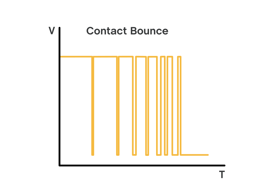
- Contact bounce: as a relay cycles, the contacts can go through multiple, very brief open/close cycles known as contact bounce, which generates electrical pulses. Depending on the sensitivity of the application, this can produce undesirable effects. Determining whether contact bounce will matter must be determined prior to specification.
Summary
Relays are proven, efficient, and effective devices that offer safe electrical control of devices and systems from a distance and also isolate the controller from the operating current. Power relays are either electromechanical or solid-state relays that have been designed with additional robust features to handle higher voltages and currents. As you determine the relay power switching requirements of your product, CUI Devices is here to address your low-level or high-level current switching needs with a wide range of power relays and signal relays.
 Tags:
Tags:
Additional Resources