Understanding and Measuring Sensitivity in Audio Components

A common specification for microphones, speakers and buzzers is sensitivity. This parameter relates electrical signals to sound pressure. Understanding the definition and significance of this parameter is important in that it helps the engineer to intelligently select the proper audio component to suit their design. It is also important to understand how to compare sensitivity specifications in the event that they have been characterized under differing measurement conditions.
What is Microphone Sensitivity?
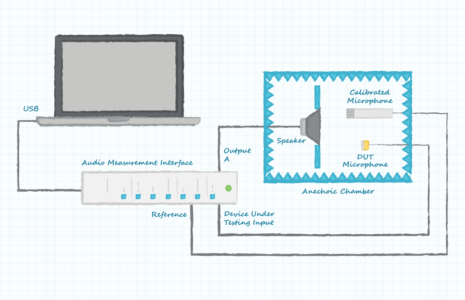
The parameter of microphone sensitivity quantifies the efficiency of a microphone in converting sound into an electrical signal. A more sensitive microphone will produce a larger output voltage when driven by a specific input sound pressure. An electronic amplifier could be used to boost the output signal from a less efficient microphone, but the amplifier will also boost undesired noise associated with the desired signal. The output voltage from the microphone under test is compared to a reference voltage and the resulting ratio is expressed in the units of dB. The equation describing microphone sensitivity is expressed as:
S = 20 log10(V/Vref)
A standard reference used for comparison is 1 Volt of output signal from the microphone with 1 Pascal of sound pressure applied to the microphone. As a brief review of measurements characterized in dB, a microphone producing 1 volt of output signal from 1 Pascal of sound pressure will have a sensitivity of 0 dB (equal to the reference). A microphone producing twice as much output voltage for the same sound pressure will have a sensitivity rating 6 dB greater while one producing 1/10 as much output voltage will have a sensitivity rating 20 dB less. Almost all microphones will have sensitivity specifications of less than 0 dB (a negative number) because the reference voltage is 1 Volt and the voltage produced by the microphone under test is typically less than 1 Volt.
The sensitivity of a microphone characterized with a pressure level other than 1 Pascal can be adjusted to the equivalent of 1 Pascal by using this formula:
Sadj = 20 log10(1/Pchar)
Where: Sadj is the adjustment to make to the characterized sensitivity Pchar is the pressure level at which the characterization was performed Examples: -70 dB at 0.1 Pa will be -50 dB at 1 Pa (-70 + 20 log10(1/0.1) = -50 dB) -60 dB at 0.5 Pa will be -54 dB at 1 Pa (-60 + 20 log10(1/0.5) = -54 dB)
What is Speaker Sensitivity?
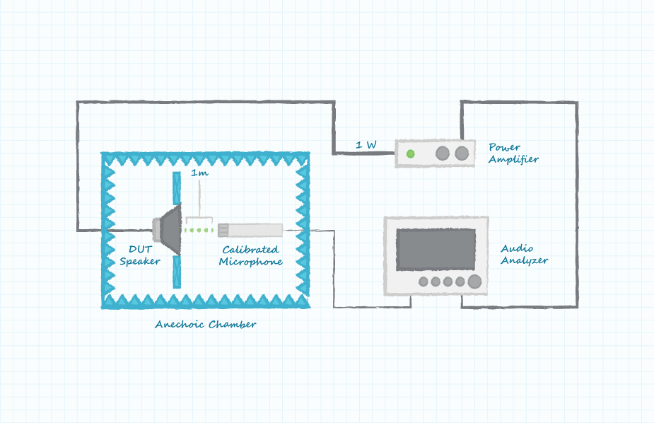
Speaker sensitivity is a measure of the ability of a speaker to convert electrical power applied to the speaker into sound pressure or volume as heard by the listener. As with a microphone, the sensitivity of a speaker can also be thought of in terms of efficiency; a more efficient speaker will produce a louder sound for a given electrical input signal. A less efficient speaker can be driven with a higher input power level, but the associated amplifier is an added cost to the design and the speaker will need to be able to handle the higher input power. The standard configuration for characterizing a speaker is to place the speaker under test in an anechoic chamber, place a microphone 1 meter in front of the speaker and then drive the speaker with a 2.83 Volt signal (1 Watt into 8 Ohms).
The equation for the sensitivity of a speaker is expressed as:
S = 20 log10(P/Pref)
Quantities P and Pref are the sound pressure produced by the speaker under test and a reference sound pressure level. The minimum sound pressure level of human hearing (20 µPa) is typically used as the reference pressure. Speaker sensitivity characterization can also be performed at conditions other than the standard 1 Watt, 1 meter and 20 µPa and the sensitivity can then be equated back to standard conditions.
Drive level
Compensating for a non-standard drive level is described by the following equations:
Sadj = 20 log10(Vstd/V) Sadj = 10 log10(Pwrstd/Pwr)
The first equation should be used if the drive signal is specified in units of Volts while the second equation applies if the drive signal is specified in units of Watts (power is proportional to Volts squared).
Examples: 70 dB at 1 V of drive signal will be 79 dB at 2.83 V (70 + 20 log10(2.83/1) = 79 dB) 80 dB at 0.1 W of drive signal will be 90 dB at 1 W (80 + 10 log10(1/0.1) = 90 dB)
Measurement distance
Compensating for a non-standard measurement distance is described by the following equation:
Sadj = 20 log10(D/Dstd)
Examples: 65 dB at 0.1 meter of measurement distance will be 45 dB at 1 meter (65 + 20 log10(0.1/1) = 45 dB) 95 dB at 30 cm of measurement distance will be 85 dB at 1 meter (95 + 20 log10(0.3/1) = 85 dB)
Reference pressure
Compensating for a non-standard reference pressure is described by the following equation:
Sadj = 20 log10(P/Pstd)
Example: 10 dB with a reference sound pressure of 1 Pa will be 104 dB with a reference sound pressure of 20 µPa (10 + 20 log10(1/20*10-6) = 104 dB)
Conversion tools can be found on the web to calculate the adjustments for non-standard test conditions. One example of such an application is our Speaker SPL Calculator.
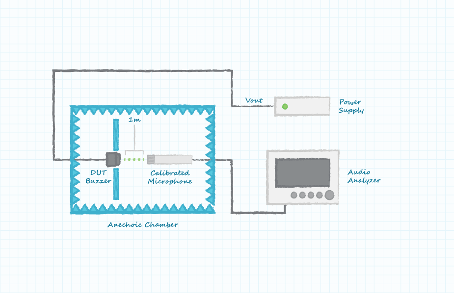
What is Buzzer Sensitivity?
In a similar manner to speakers, buzzer sensitivity is characterized by the output sound pressure produced from an input voltage. The controlled measurement conditions for buzzers are also the input drive voltage, measurement distance and reference sound pressure. The input drive voltage for a buzzer is typically the power supply voltage. Similarly, the equations used for speakers to correct for non-standard test conditions can be used for buzzers.
Conclusion
Understanding microphone, speaker and buzzer sensitivity is important when specifying or selecting them for projects as the sensitivity specifications describe the relationship between sound pressure and voltage for these components. When comparing audio components from various suppliers, it is also important to ensure that measurement conditions have been standardized. Where measurement conditions differ, simple equations enable conversions from non-standard measurement conditions to ensure a proper comparison is made.
 Tags:
Tags:
Additional Resources