Understanding Airflow Fundamentals for Proper Dc Fan Selection
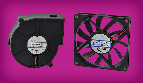
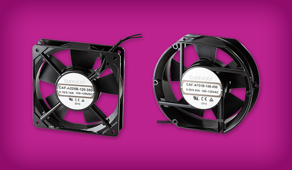
Fans have been the go-to solution in a designer's thermal management toolbox for years, providing efficient cooling for products requiring the removal of heat from a few watts to several hundred watts. To ensure that the appropriate fan is selected, it is important to align the system's cooling needs with the fan's airflow characteristics. This blog will cover the basics, including proper calculation of airflow and air pressure parameters, aligning airflow requirements with a fan's operating curve, the implications of running fans in parallel or series, and the effects of fan speed. Shop CUI Devices' full range of ac fans and dc fans.
Important Airflow Parameters
Before a fan can be specified for a particular system, there are a few parameters that are important to understand regarding airflow and heat transfer. Moving air is effective in cooling objects by absorbing heat from the object and then transferring that heat elsewhere to be dissipated. The amount of energy transferred is dependent upon the mass of the moving air, the specific heat of the moving air, and the temperature change imparted to the moving air.
Energy = Mass * Specific Heat * Temperature Rise
The mass of the moving air can be calculated from the volume of air being moved and the density of the moving air.
Mass = Volume * Density
Substituting the second equation into the first relates the energy dissipated to the volume of air involved.
Energy = (Volume * Density) * Specific Heat * Temperature Rise
Dividing both sides of the equation by time produces the following form of the equation.
Power = (Volume/Time) * Density * Specific Heat * Temperature Rise
In most applications the excess power (inefficiency of the system) is known and the airflow (volume/time) is unknown. Thus, the equation can be arranged as shown below.
Airflow = Power/(Density * Specific Heat * Temperature Rise)
As discussed in our previous blog post, this equation is commonly written as:
Q = [q/(ρ * Cp * ΔT)] * k
Where
Q = airflow
q = heat to be dissipated
ρ = density of the air
Cp = specific heat of the air
ΔT = the temperature the air will rise when absorbing the heat to be dissipated
k = a constant value, dependent upon the units used in the other parameters
The density of dry air at sea level at 68°F (20°C) is 0.075 lbs/ft3 (1.20 kg/m3) and the specific heat of dry air is 0.24 Btu/lb °F (1 kJ/kg °C). Using these values for density and specific heat the above equation simplifies to:
Qf = 3.2q/ΔTF
Qf = 1.8q/ΔTC
Qm = 0.09q/ΔTF
Qm = 0.05q/ΔTC
Where
Qf = airflow in Cubic Feet per Minute (CFM)
Qm = airflow in Cubic Meters per Minute (CMM)
q = heat to be dissipated in Watts
ΔTF = the temperature the air will rise when absorbing the heat to be dissipated in °F
ΔTC = the temperature the air will rise when absorbing the heat to be dissipated in °C
Air Pressure
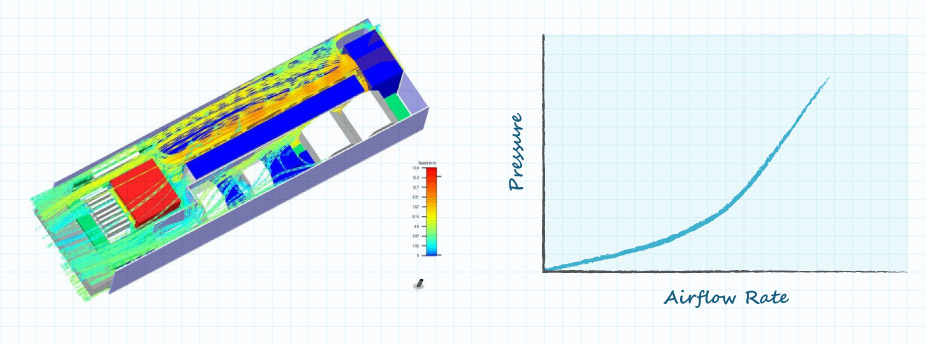
The above equations state the airflow rate required to cool a product. It is also necessary to know the pressure at which the airflow is to be delivered by the fan. The path of the airflow through the product to be cooled will create a resistance to the flow of the air. Fans should be selected to produce sufficient pressure to force the required volume of air through the product to enable the desired cooling. Calculating the required pressure will be a separate task for each unique product and cannot be simplified in a manner similar to the flow rate calculations. Many CAD products are available to calculate the air pressure and airflow characteristics of a design, while anemometers and manometers can be used to measure the air speed and pressure characteristics once a design is completed.
Achieving Required Airflow and Pressure
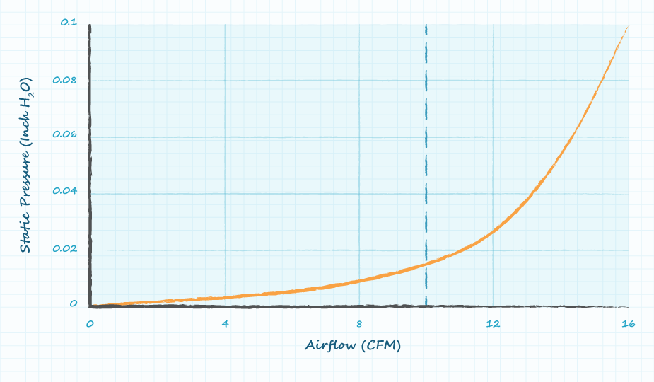
Based upon concepts from the previous two sections, an airflow rate and air pressure must be created by the fan (or fans) to provide the required cooling. Datasheets from fan manufactures will provide a value of airflow rate with no back pressure, a value of maximum pressure with no airflow rate, and a curve of the airflow versus the pressure available from the fan. Take for example a product whose airflow requirements have been calculated to be 10 CFM or greater based upon the heat to be removed and the air temperature limits. The mechanical design of the product has been characterized to produce the airflow versus pressure graph shown in figure 2. The dashed line denotes the minimum airflow required for the product (greater airflow is also acceptable), while the orange curve represents the relationship between pressure and airflow for the mechanical design of the product.
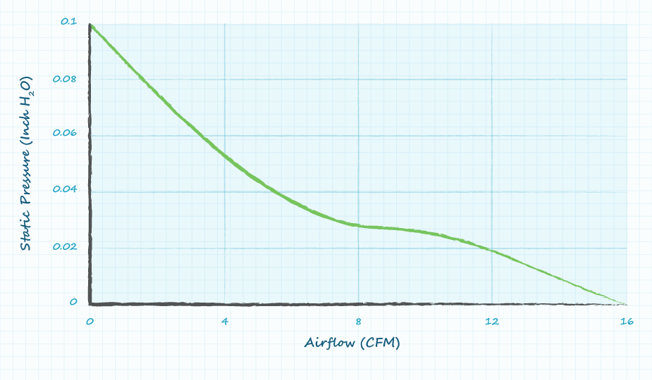
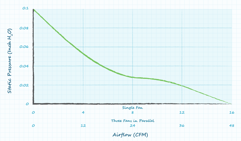
Based upon the curves in figure 2, CUI Devices' CFM-6025V-131-167 dc axial fan has been selected for the project. The datasheet for the dc fan specifies 16 CFM of airflow with no back pressure, static pressure of 0.1 inH2O with no airflow, and also provides the graph in figure 3.
Overlaying the system requirements from figure 2 on the dc fan characteristics from figure 3 produces the graph in figure 4.
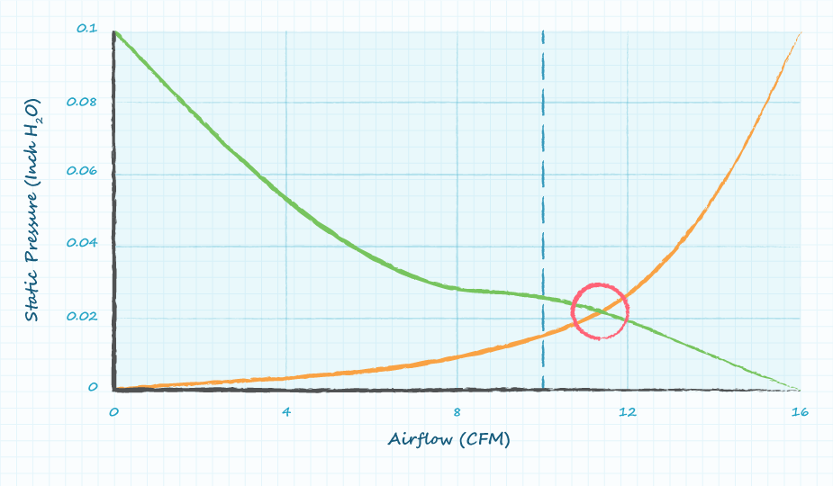
The operating point highlighted by the red circle in figure 4 indicates the pressure and airflow for the system with the selected fan. It should be noted that the airflow requirement was calculated to be 10 CFM and the fan will provide 11.5 CFM of airflow. For some applications this will be a sufficient thermal operating margin, while in other applications this solution may not provide enough margin.
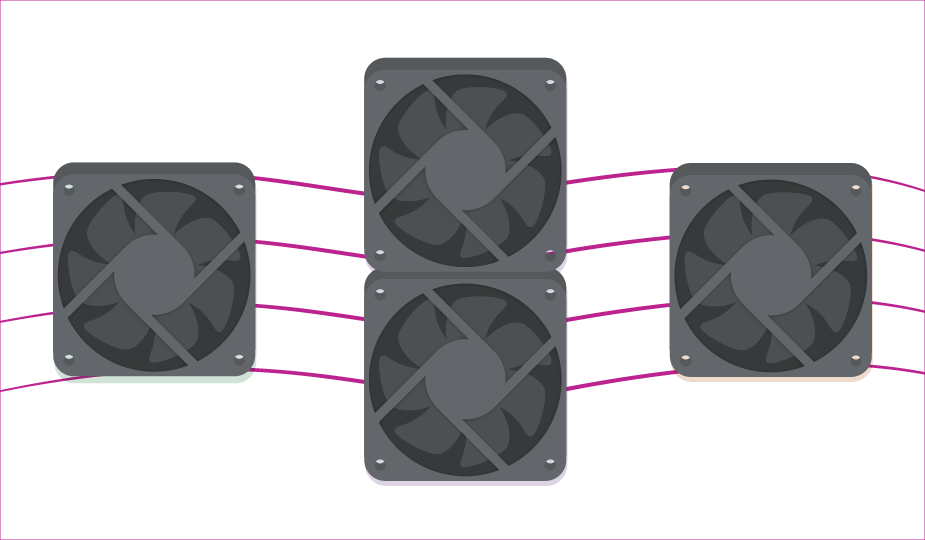
Operating Fans in Parallel or Series
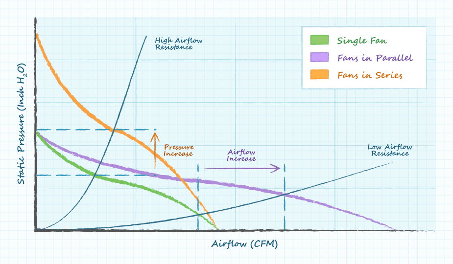
In general, larger or faster fans will provide greater maximum airflow and greater maximum pressure. If a single fan is unable to deliver the required airflow or pressure, then two or more fans can be operated physically in parallel or in series. Operating fans in parallel will increase the maximum available airflow, but will not increase the maximum pressure, whereas operating fans in series will increase the maximum available pressure, but will not increase the maximum available airflow.
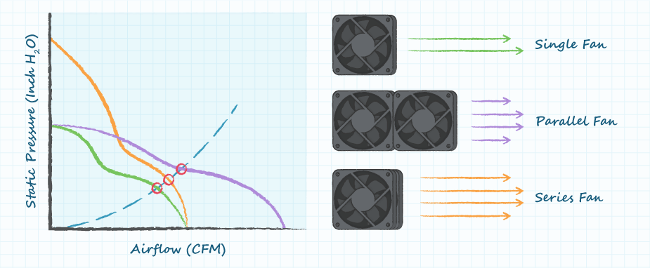
The performance curve for operating multiple fans in parallel can be easily generated by the user. The combined fan airflow versus pressure curve for multiple fans operated in parallel is identical to the single fan graph, with the only change being the values of airflow are multiplied by the number of fans operated in parallel.
The performance curve for operating multiple fans in series can be generated in a similar manner, with the pressure values altered by the number of fans in series. Ultimately, multiple fans in parallel provide the greatest improvement for high airflow and low-pressure systems, while multiple fans in series provide the greatest improvement for high pressure and low airflow systems.
Effects of Fan Speed
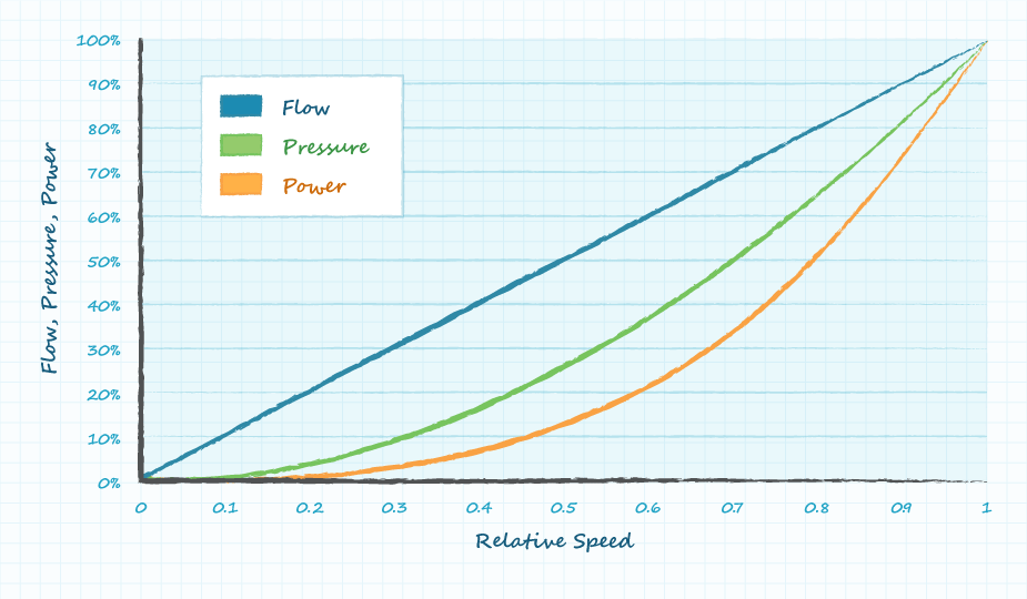
The speed of the fan (RPM) can be determined by the initial selection of the fan or by a fan control signal. Changing the speed of the fan will affect the air volume, the air pressure, the power consumed, and the acoustic noise produced by the fan. These relationships are described by what are called the "fan affinity laws".
Fan Affinity Laws
- The volume of air moved by the fan is proportional to the speed of the fan.
- CFM α RPM
- i.e. 3 x RPM produces 3 x CFM
- CFM α RPM
- The pressure of air from the fan is proportional to the square of the speed of the fan.
- Air pressure α RPM2
- i.e. 3 x RPM produces 9 x pressure
- Air pressure α RPM2
- The power required to operate a fan increases by the cube of the speed of the fan.
- Power α RPM3
- i.e. 3 x RPM requires 27 x power
- Power α RPM3
- The acoustic noise produced by a fan will increase by 15 dB when the speed of the fan is doubled.
- A 10 dB increase in acoustic noise is typically perceived by human hearing as a doubling of the noise level
Conclusion
With knowledge of the required airflow and pressure, the proper fan (or fans) can be selected to provide adequate cooling. Operating fans in parallel or in series provides designers with additional options to meet the thermal requirements of their application when a single fan may not be sufficient. CUI Devices' line of ac and dc axial fans and blowers features a variety of performance ratings, allowing designers flexibility when choosing between fan size, power consumed, audible noise produced, and more.

 Tags:
Tags:
Additional Resources