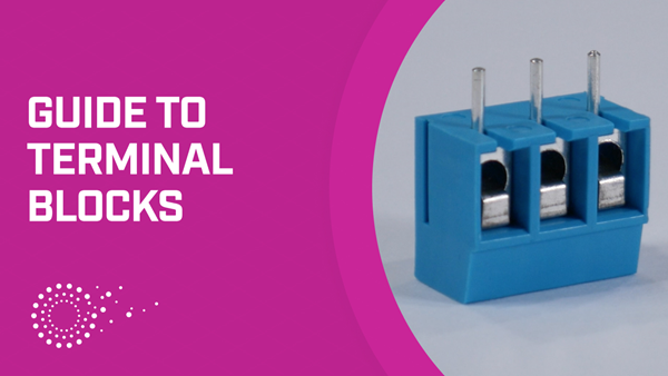
The Ultimate Guide to Terminal Block Selection
What is a Terminal Block?
A terminal block consists of a modular housing with an insulated body that secures two or more wires together. Terminal blocks—also referred to as terminal connectors, connection terminals, or screw terminals—are used in a wide array of applications where electrical systems need to be safely connected. They are ideal for designs requiring secure, well-organized, and semi-permanent wire connections that can be easily swapped out for inspection or repair in the field.
Terminal Block Types
There are various types of terminal blocks that can be used in a design. These are some of the most common:
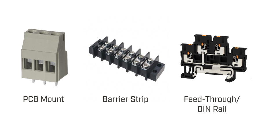
PCB Mount
Often referred to as Eurostyle or wire-to-board terminal blocks, PCB mount terminal blocks work by inserting bare wires into the module where a clamp secures the wire in the housing. The housing is then soldered to a PCB in common footprints. PCB mount terminal blocks can be single, dual, or multi-level modules.
Barrier Strips
These terminal blocks have a screw down terminal where a ring or spade terminal is attached to the wire and then inserted onto the screw and tightened into the housing. Barrier strips are commonly used where vibration is a concern.
Feed-Through/DIN Rail
Feed-through terminal blocks are used to connect two wires together for wire-to-wire connections. This terminal block type has one input and one output contact where two distinct wires are fed into opposite sides of the housing. Like PCB mount versions, these can also be single, dual, or multi-level modules. The feed-through style is most commonly found in DIN rail mount configurations. DIN rail terminal blocks are typically offered as a feed-through type for wire-to-wire connections or ground type, which visually looks the same as a feed-through style, but instead of connecting the incoming wires, it grounds them to the DIN rail or panel.
Key Terminal Block Electrical Considerations
When designing a system that will utilize a terminal block, you will likely know your overall system voltage and current requirements. While these are very important, there are other factors to consider in your design as detailed below.
Current Rating
The current rating is often the most important parameter to consider in terminal block designs. The current rating is based on the conductivity of the terminals, cross-sectional area, and the corresponding heat rise. Operating at too high of a current can cause overheating and damage of the terminal block, leading to major safety concerns. It is best practice to use a terminal block that is rated for at least 150% of the max current that is expected in the system.
Voltage Rating
The voltage rating is in part determined by the dielectric strength and pitch of the terminal block housing. The maximum system voltage of the application must be less than the voltage rating. Any voltage surges in the system should also be evaluated when selecting the terminal block.
Pole Count
The number of individual circuits within the terminal block is also known as the pole count. This can be as few as a single pole, and as high as 24 poles and beyond, based on how many individual circuits are needed in the specific application.
Pitch
A terminal block’s pitch is defined as the center distance from one pole to the next. The pitch of the connector is often determined by the overall rating of the terminal block where factors like voltage/current, creepage, and clearance are considered. Common industry pitches would be, but are not limited to, 2.54 mm, 3.81 mm, 5.0 mm, and 7.62 mm.
Wire Size/Type
The minimum and maximum wire size that the terminal block can accept would be a function of the voltage/current rating. In addition to making sure the wires used will physically fit into the terminal block, the type of wire should also be considered. Stranded or multi-core wire is typically used for screw terminals, and single-core is typically used for push-in style terminal blocks. In North America wire size is specified in units of American wire gauge (AWG). Wire size can also be specified as mm2.
Key Terminal Block Mechanical Considerations
In addition to system electrical factors, mechanical restrictions and limitations need to be considered in terminal block design. The key features to consider are any mechanical restrictions on the housing of the design that may impact overall footprint, orientation, and accessibility of the connections. Mechanical variations to the housing can include, but are not limited to, the following.
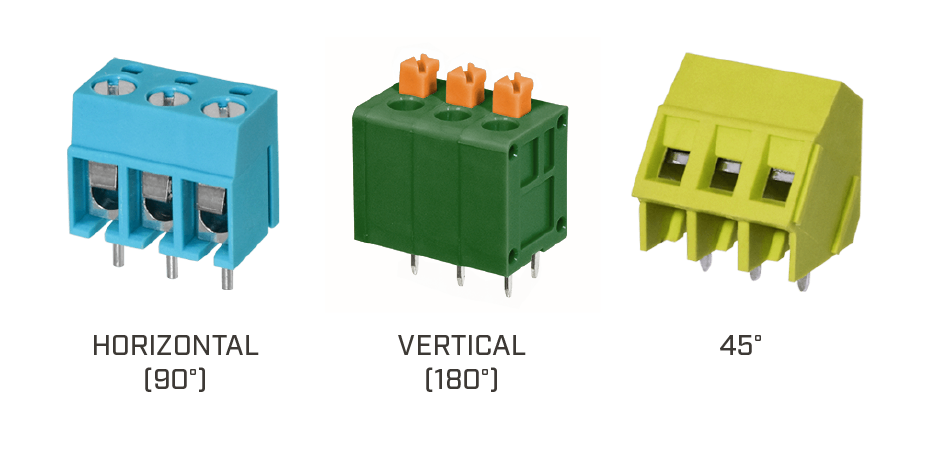
Wire-Entry Orientation
Terminal blocks come available in three common orientations: horizontal, vertical, and 45°. Horizontal and vertical are also known as 90° and 180°, respectively. The wire orientation can often be determined by physical restrictions in the overall design that make one option more feasible than the other.
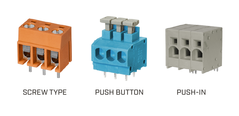
Wire-Securing Method
The method in which the wires are secured in the terminal block housing are typically accomplished by three main types: screw terminal, push button, or push in.
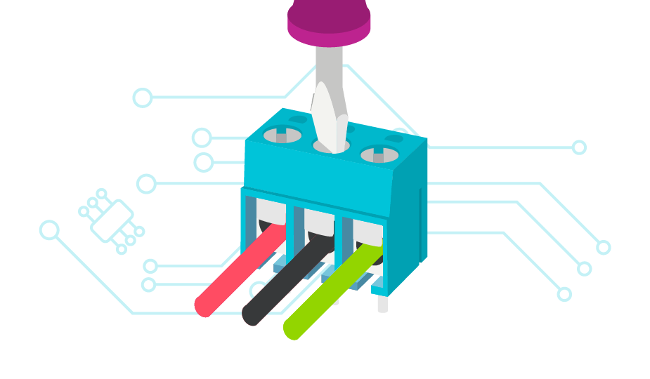
- Screw Terminal
Screw terminal or screw type terminal blocks secure the wire against the conductor in the terminal block by tightening a screw which closes the clamp. - Push Button
Push button terminal blocks secure the wire against the conductor by a spring clamp that is opened by pressing a button. Releasing the button clamps the spring onto the wire. - Push-In
Similar to the push button with a spring clamp, a push-in terminal block allows the wire to be pressed directly into the housing without the use of a push button to open the spring.
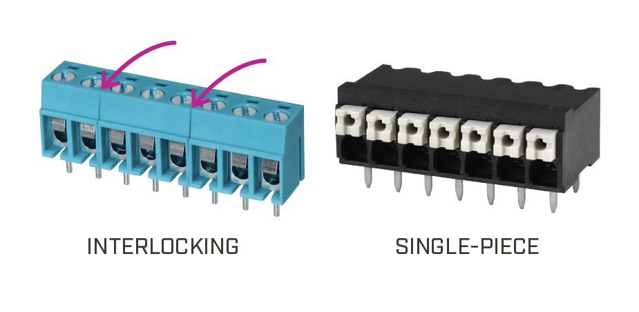
Module Type
Terminal block modules can be constructed in pieces that are interlocked with one another, or in single housings. Interlocking terminal block modules are typically constructed in 2 and 3 pole versions. With these two sizes, a designer can achieve any pole count that is needed by just snapping the modules together. DIN rail terminal blocks operate in much the same way by sliding individual units together on the metal rail. Once the desired configuration and number of poles is achieved, they are then finished with a compatible end cap to protect the housing on the outer most units.
Single-piece terminal blocks are constructed in a way that all poles are contained in a single housing. These are typical for pluggable housings where it would not be feasible to have multiple pieces. Other uses include high current or high temperature versions where a single housing would be stronger.
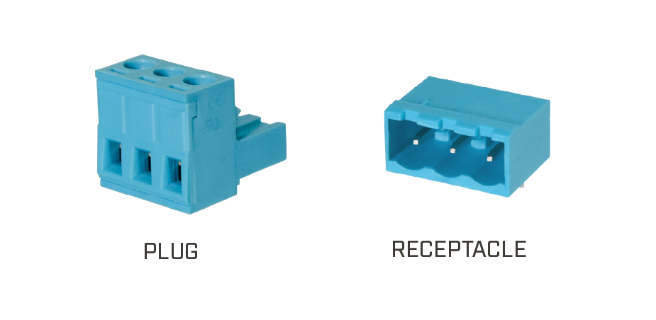
Wire-to-Housing Method
While most terminal block connectors have wires inserted directly into the housing, there are some variations that utilize mating pairs that can be plugged together. These pluggable terminal blocks still have the wires inserted into a housing, but with the additional benefit of a modular housing that can be plugged directly into a fixed housing on a PCB. These simplify designs where the main connections need to be disconnected frequently without having to disconnect all individual wires.
Safety Ratings
Terminal blocks are typically certified and/or designed to UL and/or IEC safety standards and are composed of materials that have a flammability rating meeting UL94V-0. Both UL and IEC ratings can appear on a datasheet with differing values. This is because each agency uses a different standard and requirements that a terminal block must meet. When selecting a terminal block, you will want to know your overall system safety requirements, and make sure the terminal block ratings comply with them.
Other Design Considerations
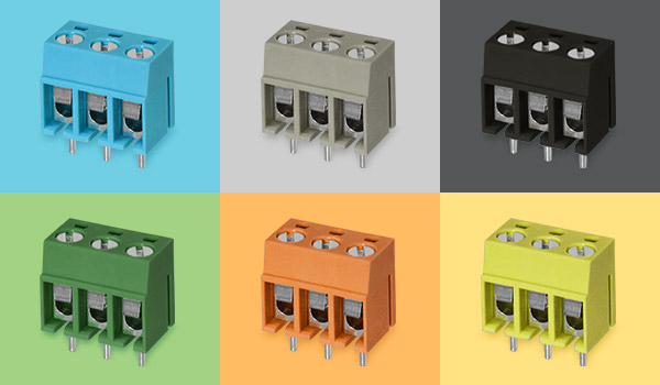
In order to make assembly or maintenance easier for the user, housing color or special markings can be modified to help differentiate various terminal block connections. This is especially useful for more complex systems that utilize multiple wiring and circuits housed in a centralized location.
Operating temperature of the end system also needs to be considered to know whether a high temperature rated terminal block would be needed.
Conclusion
While there are many factors to consider when designing an overall system, terminal blocks are an optimal solution for complex electrical system connections. With a variety of color options and configurations, CUI Devices’ terminal blocks offer a range of options to meet your design challenges.
 Tags:
Tags:
Additional Resources