The Basics of Circular Connectors and Cables
What Are Circular Connectors?
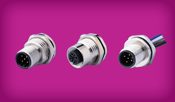
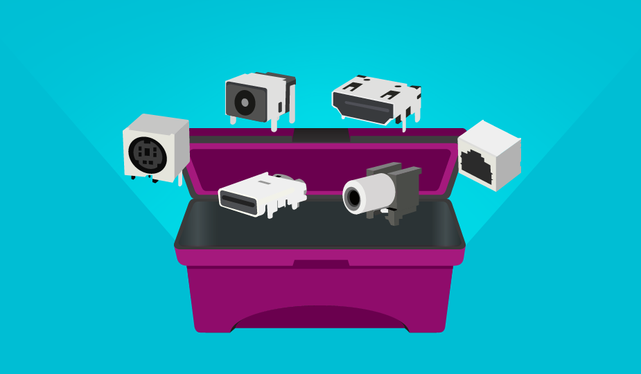
Circular connectors are cylindrical electrical devices of varying size with circular mating surfaces. They contain multiple pins, or contacts that connect with applicable parts to transfer electrical power, signals, or data. They may also be referred to as circular interconnects. The internal contacts are mated with wire or cable to carry a signal.
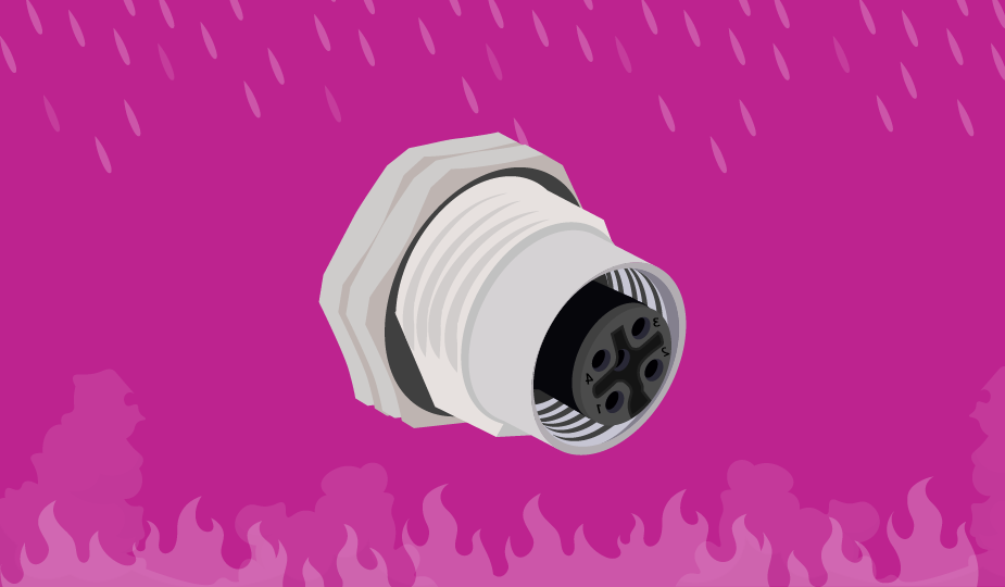
Their cylindrical or tube-shaped bodies make these connectors especially rugged and resistant to vibration and impact damage, temperature and pressure extremes, outside signals or interference, and incursion from dust or gasses.
The array of modern products currently available in this category ranges from simple plastic, metal, or composite standard circular connectors to many other types, including DIN, Metric, Hermetic, Push-Pull, Keyed, Mixed Signal, and Micro or Nano versions. Hybrid options are available that combine power, signal, and data into a single device. Modular or custom solutions can also be found that tailor a connector product to a specific application. Shop CUI Devices' full range of circular connectors and circular cable assemblies.
Characteristics of Circular Connectors
Their tube or cylindrical shape gives circular connectors a higher strength to weight ratio than any other shape. This inherent strength allows for resistance to outside elements, impact damage, and accidental decoupling. This strength also makes them useful and resilient in applications requiring frequent mating cycles. The number of internal pins or contacts are varied by application, and the layout of the contacts or internal keys assures proper alignment and insertion into a mating device.
Circular connectors are most often (but not always) connected by threaded areas on the shells. This screw-in connection allows them to be easily and securely locked into position and remain in place despite vibration or impact. Other types of connection systems include bayonet locking, push/pull locking, and snap lock.
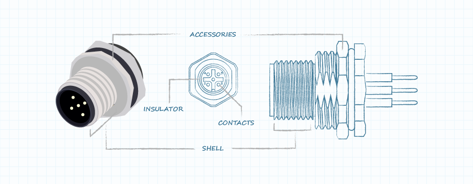
The basic structure of a circular connector includes the following:
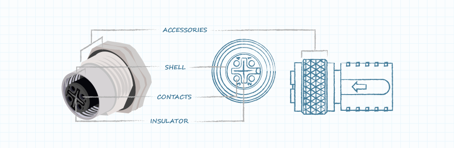
- Contacts – these are the pins and sockets housed internally in the connector that mate with each other to form an electrical connection. A contact pair is composed of a male contact pin and a female socket.
- Insulator - this is the material used to encapsulate the contacts and insulate them from each other and the connector shell. This material also serves to hold the contacts in the correct position in the shell and properly spaces them from each other.
- Shell – this is the outer cover of the connector and serves to house the contacts and insulator. It also provides alignment when mating the connector halves and secures the connector sections to each other or to a device.
- Accessories – these are the additional components that are used to position, guide, clamp, secure, or seal the parts of the connector. They include pins, rings, keys, clamps, gaskets, and more.
Broad Uses of Circular Connectors
Circular connectors, due to their high performance in extremes of vibration, shock, temperature, pressure, and interference (EMI & RFI) are finding increased use in many industrial applications requiring electric power transmission, signal transmission, data transfer, and mixed signal transmission (power + signal + data). They are best used when rugged construction of the connector is necessary, when ingress protection is warranted, when a secure mating system is required, or when protection from EMI or RFI is necessary.
M5 vs. M8 vs. M12 Designations and Codes
M-style circular connectors are a series of standard product types used for connecting sensors and actuators in industrial network applications. They are designed to perform in extreme conditions. The “M” designation refers to the size of the metric thread on the coupling nuts and mating receptacles, and thus the relative size of the connectors. M5 connectors have 5 mm diameter fasteners, M8 have 8 mm fasteners, and M12 have 12 mm fasteners.
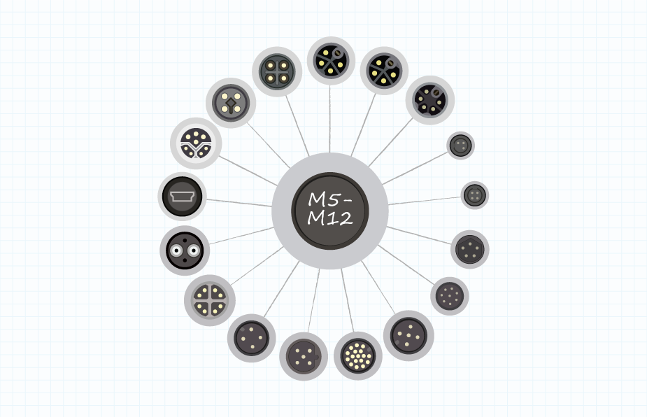
M12 circular connectors and cables are the most used size and are a global standard for the automotive industry. They are further divided into additional categories based on the keying or shape of the contact body. The various M12 codes ensure that cables are mounted with the correct connectors. The different codes used and their definitions are the following:
- A – connectors for sensors, dc power and 1 Gbit Ethernet (protocol for connecting computer systems to form a network).
- B – connectors for Fieldbus (industrial computer network for distributed control) and Profibus (digital network standard providing communication between field sensors and a control system).
- C – connectors with a dual keyway for added security, used for ac power for sensors and actuators.
- D – connectors for 100 Mbit Ethernet and Profinet (protocol for data exchange between controllers and devices) systems.
- X – connectors for 10 Gbit Ethernet high speed applications as well as power over Ethernet (PoE).
- S – connectors for ac power (replacement for C – coded parts).
- T – connectors for dc power (replacement for A – coded parts).
Applicable Standards for Circular Connectors
Circular connectors are designed and manufactured in compliance with several different national and international standards organizations. Here are some of the standards bodies and designations involved with the development and continued use of these products:
- UL – Underwriter’s Laboratories standards pertaining to circular connectors (UL1977 & UL2238) cover safety issues and properties of materials used in manufacturing.
- IEC – International Electrotechnical Commission standards define and describe several types of circular connectors, including IEC 61076-2-113 that defines the requirements for M12 connectors.
- MIL/AERO – Military Standards for circular connectors were developed by the U.S. Department of Defense in the 1930’s and cover design and test requirements for a broad array of connectors, including circular devices.
- EN – European Standards (European Norm) cover circular connector details in EN- IEC 61076. Other standards cover connector specifications by application.
- IP – Ingress Protection ratings are defined by the IEC 60529 standard that covers protection against solids and liquids entering the body of the connector. ANSI 60529 covers IP in the United States and EN 60529 covers it in Europe.
- DIN – German National Standards Organization (Deutsches Institut fur Normung) standards cover circular connectors specifically in DIN 41524 and other documents.
- VARAN – Versatile Automation Random Access Network is a bus system based on Ethernet that is implemented in hardware for machine automation, including circular connectors.
Selection Criteria for Circular Connectors
There are numerous criteria to consider when you are specifying circular connectors for a new design or a re-design. The first is whether your design requires a circular plastic connector (CPC), or a circular metal-shell connector (CMC). Beyond this, here is a non-exhaustive list of parameters in random order that you will need to decide on:
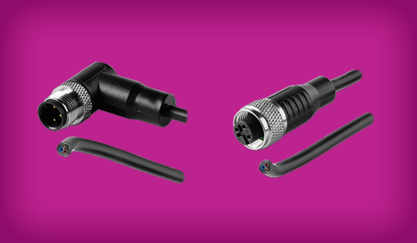
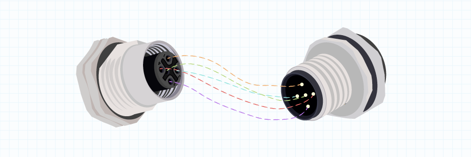
- Gender (Male/Female): The male part incorporates the contact pins that plug into the sockets in the receptacle, or female portion. Most plugs and receptacles are designed to mate within their own brand, or manufactured product line. Typically, connectors from different manufacturers do not interconnect. You will typically be sourcing connectors as a mated pair, but not always.
Male and female matching of circular connectors - Number of Contacts: The number of conductive pins or contacts that your design requires in the connector to carry the signals, data, or power you need to move.
- Termination: This is how your wire or cable will mate with the conductive contacts in the connector. Some options include solder, wire wrap, lugs, or crimping.
- Contact Size: The diameter of the individual contacts, or the gauge of the wire that can mate with each contact.
- Voltage & Current Rating: The maximum voltage or current that the connector is designed to carry. Current rating is the flow of electricity, expressed as amps (A). Voltage rating is the amount of voltage that can be safely carried, expressed as volts (V).
- Insertion Frequency: The regularity of connection and disconnection of the connector (also known as mating cycles). Frequent mating cycles may require a more robust connector or cable protection accessory.
- Mounting Type: How the connector will be mounted, including cable mount, panel mount or circuit board mount. Different mounting hardware applies to each type.
- Coupling or Locking Style: How the connector will be securely mated. Locking styles include bayonet, latch, push-pull, threaded, and quick-disconnect.
- Type of Backshell: The connector backshell is threaded onto the cable side of a circular connector to provide secure cable support. Many different types of backshells are available, including straight, right angle, braid tail, spring, strain relief, sealed and crimped.
- Environmental Factors: Will the connector be exposed to liquids, gasses, or subject to immersion? Does the connector require protection from EMI or RFI signals? Will the connector come in contact with caustic chemicals, excessive vibration or frequent impacts? The answers to each of these will help determine the quality, features, and accessories you may need.
- Materials Used: Connector bodies can be stainless steel, aluminum, plastic, composite, or brass, depending on your requirements and budget.
- Accessories: Connector manufacturers offer many different types of accessories that add to the functionality of their products. The list of these is quite long, but some examples include seals, boots, and caps to lock out liquids and gasses, strain reliefs and cable clamps to protect cable disconnect, backshells to protect connections, flanges, gaskets, and grommets for installation, and cable grips for easier insertion/removal.
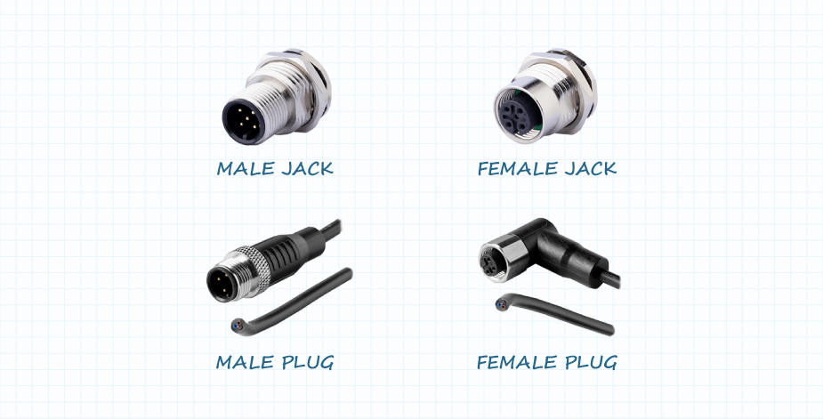
- Plugs & Sockets: While there are variations in industry standards, typically sockets and jacks are associated with panel mounted connectors while plugs are connectors that are part of cable assemblies. Again, there is no standard convention for this naming so different manufacturers may use alternate terms.
Application Examples
Uses for circular connectors have been expanding ever since their introduction for military applications in the 1930’s. For example, today’s process control systems and factory floor sensor networks, often in harsh environments, demand interconnect products that reliably function under challenging conditions.
Electronic medical equipment also incorporates circular connectors to make sure cables are always connected correctly by the hospital staff and do not come loose when a patient is moved. Some of the many other application areas that enjoy the benefits of connectivity using circular connectors include:
- Process Control & Industrial Automation
- Factory Wiring
- Transportation
- Aerospace & Defense
- Medical Equipment
- Robotics
- Audio/Video Communications
- Radio & TV Communication
- Energy
- Unmanned Aerial Vehicles
- Test & Measurement
Summary
Circular connectors have been in use for many years and have proven themselves to be reliable components that can function in a variety of harsh environments. CUI Devices offers a diverse range of circular connectors and cables that can meet the challenges of nearly any application.
 Tags:
Tags:
Additional Resources