DIP Switches 101
DIP switches have been around since the 1970s as electromechanical devices that allow users to make manual changes to an electronic circuit. The simplicity, flexibility, and low cost of DIP switches have ensured their long-standing use in several electronics applications. They come in a variety of sizes, configurations, switching mechanisms, and power ratings.
Customers can choose the number of positions on their DIP switch based on the configuration options for their application. Some DIP switches can be actuated by hand, while others require a special tool or screwdriver to toggle the switch position.
What is a DIP Switch, and How Does it Work?
A DIP switch is a dual in-line package switch, meaning that it consists of a series of switches in a single unit. It is an electromechanical device requiring a user to manually move the actuator so that a different electronic circuit is activated or deactivated. Commonly mounted on a PCB or breadboard, DIP switches allow users to quickly preconfigure or toggle an electronic device between a variety of settings or operating modes.
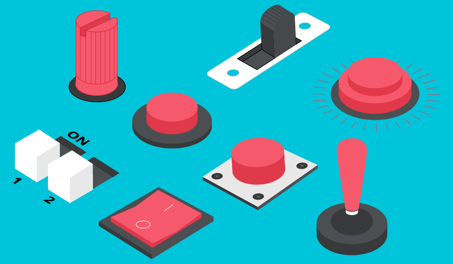
When referring to any switch, consideration must be given to the principle of poles and throws. A single pole, single throw (SPST) switch implies that the device sits in an electronic circuit where it is either closed and allows current to flow or open and interrupts the current flow.
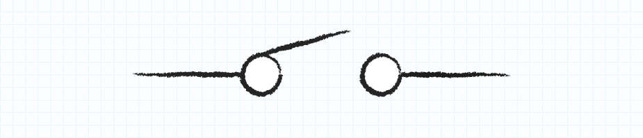
A single pole, double throw (SPDT) switch selects between two different paths for current to flow. In other words, moving the actuator does not interrupt the current flow but instead redirects it into a different circuit branch.

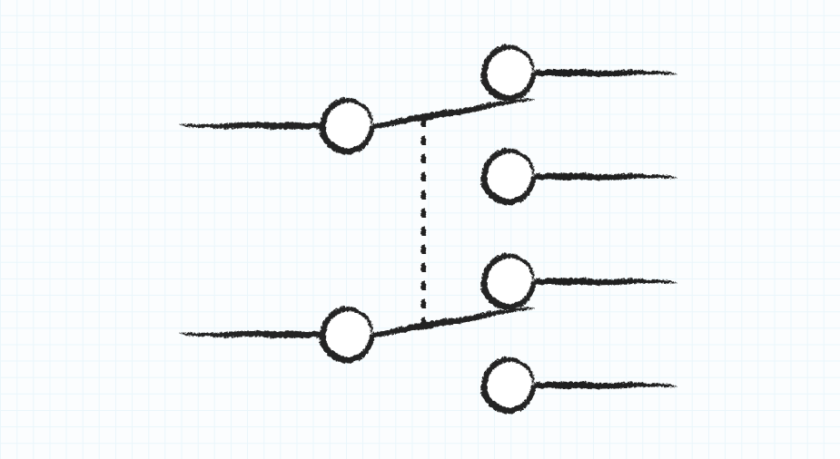
Double pole, double throw (DPDT) switches control two circuits using two linked switches. When one switch toggles position, the other does the same. Each one redirects the current into a different path within its circuit. Technically, several switches can be connected in this arrangement allowing for multiple poles and multiple throws.
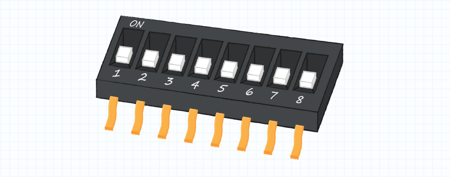
The number of switches in a package depends on the application and can range from 1 to 16 positions or more. A common DIP switch package has eight positions because it corresponds to 256 possible binary codes, which is equivalent to one byte of data. For more on switch functions and common switch types, check out our Fundamentals of Switches blog.
Types of DIP Switches
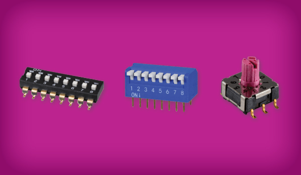
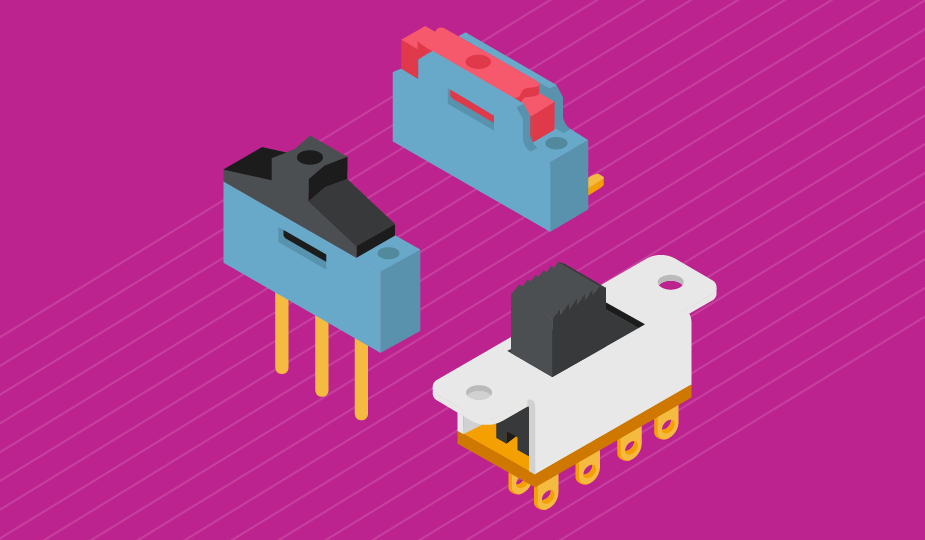
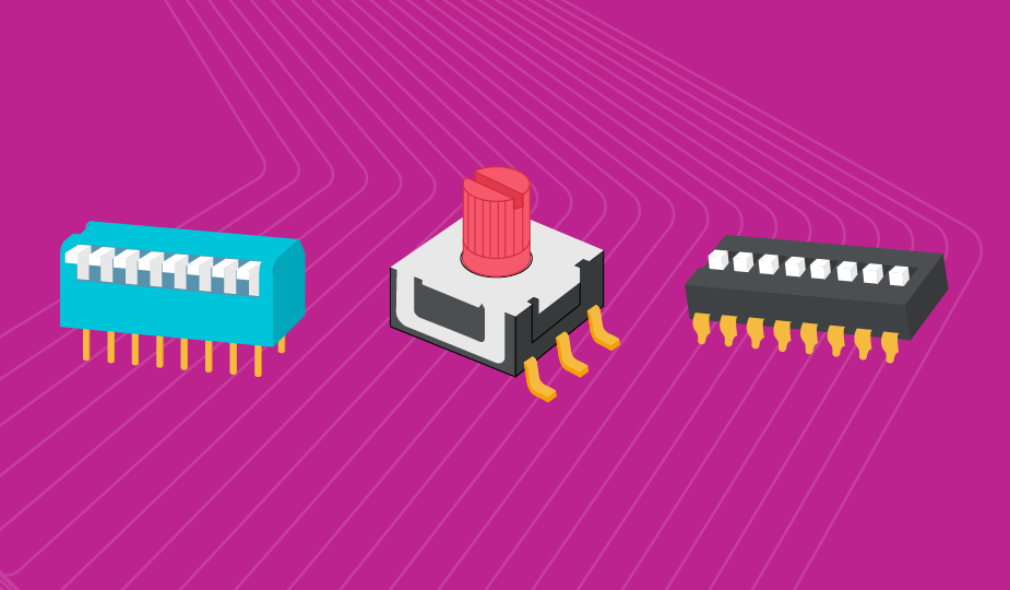
DIP switches come in a variety of types, including slide actuators, piano actuators, rotary actuators, and more.
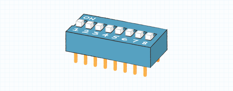
Slide DIP switches are standard toggle switches. Each switch has two positions - either closed or open (also on/off or 1/0) and therefore operates as an SPST switch. There are also three-position slide DIP switches with a central neutral location and a contact at each end, typically configured as on/off/on. Any DIP switch can be configured as normally open (NO) or normally closed (NC). Normally open switches complete the circuit when actuated, while normally closed switches break the circuit when actuated.
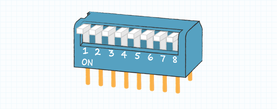
Piano DIP switches are similar to slide DIP switches. However, instead of lying horizontal, with a forward and backward motion to move the actuator, piano DIP switches are vertical, requiring an up and down action.
Rotary DIP switches toggle position as the user turns the actuator in a circular motion. The amount of rotation determines the output of the switch. A rotary DIP switch with four output pins can produce up to 16 different output configurations in binary code. It can also be configured to operate as an SPDT device and may have three or four throws for a single pole.
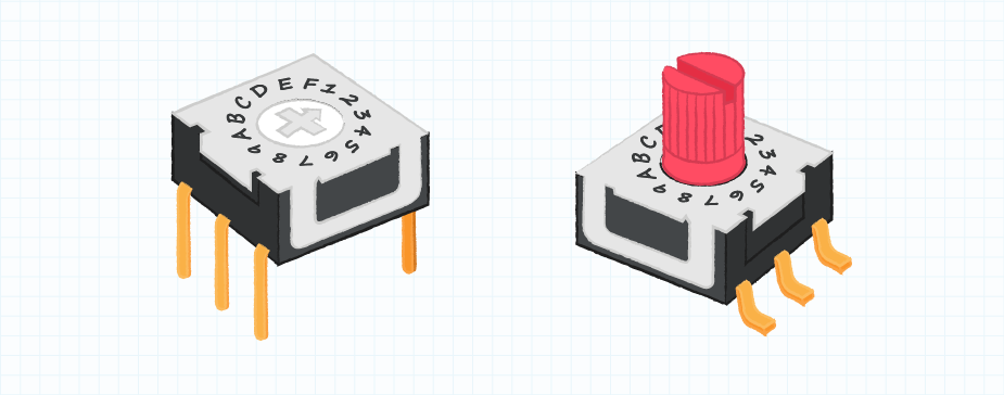
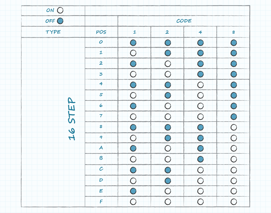
A 16-position rotary DIP switch uses a hexadecimal code of 16 symbols to describe an output combination. The hexadecimal code uses numbers 0 to 9 and then letters A to F as illustrated on the graphic below.
Some other types of DIP switches include rocker actuators, which operate like a seesaw. The switching mechanism rocks between two positions, where lowering one side of the actuator lifts the other side. This simply makes them another variation of the basic toggle switch.
Key DIP Switch Specifications
Manufacturer datasheets provide essential performance and specification information about each DIP switch. This information is vital for choosing the best DIP switch for a particular application. Outside of the obvious specifications like number of positions and actuator type, here are some additional specifications to keep in mind:
| Specification | Typical Offering | Description |
|---|---|---|
| Mounting Style | Surface or through hole | Surface mounted DIP switches are suitable for PCBs while through hole versions are used on breadboards |
| Termination Style | Gull wing, angled gull wing, J-hook gull wing, PC pin, and crimped PC pin | Allow for different mounting options |
| Voltage Rating | 2.4 to 50 Vdc | Maximum voltage across the device. Voltage ratings often list both a switching and non-switching voltage. Switching ratings indicate when the actuator is moving from one position to the next. Non-switching ratings are when the actuator is in a stationary position and will generally be higher than the switching rating |
| Current Rating | 10 to 200 mA | Maximum current through the device |
| Pitch | 1 to 2.54 mm or 0.039 to 0.1” | The center-to-center distance between pins |
| IP Rating | Rated or non-rated | DIP switches can resist moisture and dust ingress |
It is important to ensure that a selected DIP switch matches a design’s performance criteria. Using a DIP switch outside of its specifications can lead to problems like electrical arcing or self-welding. The device could also be compromised in terms of performance or even rendered inoperable.
DIP Switch Applications
DIP switches have been used in a wide variety of applications for several decades. They have even found new uses in IoT devices as a quick way to preconfigure or reprogram a device prior to its implementation in a smart home or factory, thus limiting downtime. Some of the most common applications for DIP switches are as follows:
- Programming garage door openers
- Programming remote controls
- Configuration of options on PC expansion cards or motherboards
- Adding new items to an IoT network through easy user configuration
- Checking the configuration of industrial equipment without the need to power up the equipment
Conclusion
The DIP switch was first introduced as a simple way to change the characteristics of an electronic system. It allows changes to the configuration during manufacturing or by the user. Over time, the advance of software switches and user interfaces have reduced their general use, but they remain well suited in a variety of electromechanical devices due to their low cost and ease of use.
By understanding DIP switches and the variations available, these applications can configure devices to perform specific functions and communicate with other matching devices.
 Tags:
Tags:
Additional Resources