Capacitive, Magnetic, and Optical Encoders – Comparing the Technologies
When it comes to precision motion control, an encoder is an essential component that translates mechanical motion into electrical signals. Used in many applications such as automation equipment, industrial process control, or robotics, encoders provide data on position, speed, distance, and direction. There are three main encoder technologies on the market to choose from: magnetic, optical, and capacitive. This blog will describe the operating principles of each technology and highlight some of the inherent advantages of capacitive encoder technology.
Characteristics of the Primary Encoder Technologies
Magnetic Encoders
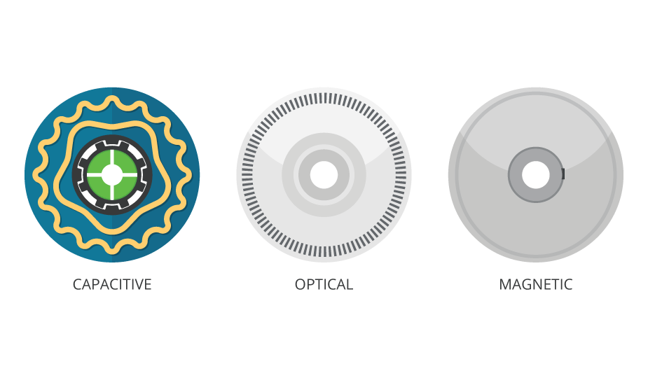
Comprised of a spinning magnetized disk with alternating poles and a hall-effect or magneto-resistive sensor, a magnetic encoder operates by detecting changes in magnetic flux fields. The magnetic encoder is rugged and copes very well with shock and vibration, while being unaffected by the ingress of oil, dirt, and moisture. On the downside, they are susceptible to magnetic interference caused by electric motors and have a limited viable operating temperature range. While many improvements have been made to magnetic encoders, they typically deliver lower resolution and accuracy than optical and capacitive alternatives.
Optical Encoders
Compared to a magnetic encoder, an optical encoder can offer higher resolution and higher accuracy. An optical encoder consists of an LED light source (typically infrared) and photodetectors located on opposing sides of an encoder disk made of glass or plastic. The encoder disk contains a series of alternating transparent and opaque lines or slots. As the disk turns, the on/off passing of light through the windows provides the typical square wave A & B quadrature pulses. Although optical encoders have dominated the motion control market for decades, these devices also have inherent disadvantages. Because an optical encoder relies on "line of sight," they are particularly susceptible to dust, dirt, and oil. Optical disks are typically constructed using either glass or plastic, making them prone to damage from vibrations and temperature extremes, as well as contamination during the assembly process onto a motor. In operation, an optical encoder also consumes current upwards of 100 mA and its lifetime is ultimately limited by the LED.
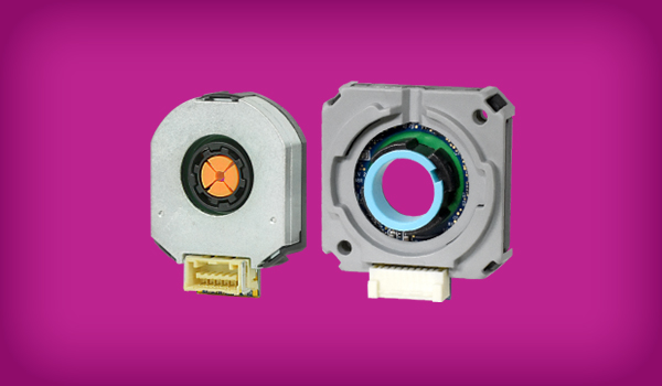
Capacitive Encoders
A capacitive encoder is comprised of three main components: a rotor, a stationary transmitter, and a stationary receiver. The rotor contains a sinusoidal pattern and, as it rotates, the high frequency reference signal of the transmitter is modulated in a predictable way. The encoder detects the changes in capacitance-reactance on the receiver board and translates them, using a demodulation algorithm, into increments of rotary motion.
Advantages of Capacitive Encoders
Derived from the same principles used in digital callipers, capacitive encoders have an excellent track record since CUI Devices launched the first generation in 2006. The AMT series has proven to be both highly reliable and accurate, solving many application issues experienced in optical and magnetic technologies. A capacitive encoder is more rugged than an optical encoder, tolerating a range of environmental contaminants such as dust, dirt, and oil. Capacitive encoders also hold-up much better to vibration and temperature extremes. Further, with no LED, it has a longer lifetime, a smaller footprint, and lower current consumption (6 to 18 mA) than an optical encoder. Immune to magnetic interference and electrical noise, it is as rugged as a magnetic encoder, but delivers greater accuracy and higher resolution.
Given their digital nature, capacitive encoders also offer increased flexibility, allowing users to change the encoder's resolution. With other technologies, the resolution is determined by the encoder disk. This means that an optical or magnetic encoder must be swapped out each time a different resolution is needed. The programmable resolutions available in capacitive encoders are not only useful for system optimization, particularly when designing the PID control loop, but can reduce inventory holding, as one model can be used across multiple applications. Capacitive technology also allows the ability to digitally set the index pulse and alignment of the encoder for BLDC commutation, while its built-in diagnostic capabilities provide designers access to valuable system data for quick troubleshooting in the field.
| Capacitive | Optical | Magnetic | |
|---|---|---|---|
| Resistance to Dirt, Dust, Oil | High | Low | High |
| Accuracy | High | High | Low |
| Temperature Range | Wide | Medium | Narrow |
| Current Consumption | Low | High | Medium |
| Programmability | Yes | No | No |
| Package Size | Small | Medium | Medium |
| EMC Immunity | High | High | High |
| Magnetic Immunity | High | High | Low |
| Resolution Range | Wide | Wide | Narrow |
Comparing the trade-offs between encoder technologies
Resolving the Trade-offs
No matter the system requirements, a capacitive encoder provides a versatile, cost-effective, and reliable alternative to either optical or magnetic sensing technologies. Not only does capacitive encoding deliver superior performance in terms of accuracy and reliability in virtually any environmental condition, but its inherent digital operation also provides programmability and enhanced diagnostic capabilities, while remaining compatible with traditional encoder functionality.
 Tags:
Tags:
Additional Resources