Understanding the Impact of Resonance and Resonant Frequency in Audio Design
Nearly all engineers are familiar with the concept of resonance and its many implications in system design. Electrical, mechanical, or mixed-mode resonance can be leveraged to provide design benefits or can be detrimental and negatively impact overall performance. This blog will provide a review of resonance-related issues including resonant frequency, factors affecting resonance in audio devices, how to use a frequency response curve, and challenges related to self-resonance in buzzers and speakers. Shop CUI Devices' full range of audio components.
What is Resonance and Resonant Frequency?
Resonance occurs when a physical object or electronic circuit absorbs energy from an initial displacement or source, and then maintains the resultant mechanical or electrical vibrations without an additional force or energy acting on it. The frequency at which this vibration occurs is known as the resonant frequency, designated F0.
Examples of Resonance
Resonance is a physical phenomenon which appears in many forms and can occur anywhere in the frequency spectrum from low audio to GHz-level RF frequencies. Here are just a few examples of resonance in practice:
- A child’s swing represents a resonant pendulum with frequency determined by the length of its rope.
- Some lasers utilize resonance based on reflections between opposed mirrored surfaces.
- In mechanical systems, a machine may shake and vibrate excessively at its resonant frequency as its motor speed increases from lower to higher RPMs.
- In electronics, a stimulated LC filter will resonate as a tuned tank circuit to establish an operating frequency.
- A piezoelectric crystal oscillator providing a system or synthesizer clock is an example of electromechanical resonance.
- A speaker will have a resonant frequency at which it is most efficient at converting the input electrical power to audio output power.
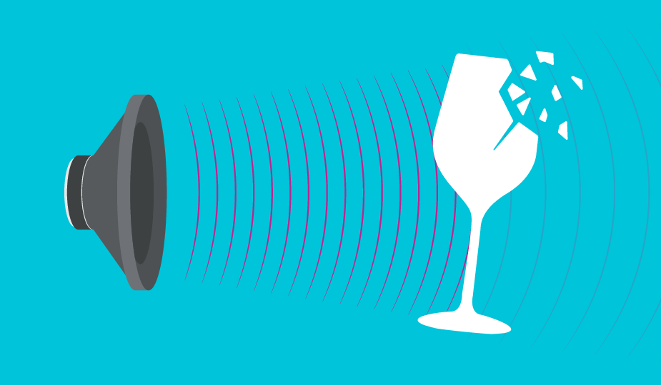
As with so many system attributes, resonance can be good and utilized to emphasize a desired attribute, or a problem that needs to be managed and even suppressed. It enables the basic function of LC tank circuits and crystal oscillators, yet it can cause self-destruction in the case of machinery. For audio sources such as buzzers or speakers, it maximizes SPL but also can contribute to unwanted harmonics, which at times creates an annoying buzz and rattle with the enclosure or surrounding objects.
Resonant Frequencies of Audio Components
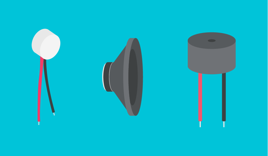
Mechanical resonance is affected by weight and the stiffness that connects different masses together. In the case of a standard speaker, the mass under consideration would be the cone (or diaphragm) and the stiffness would be dependent on the flexibility of the suspension that connects the cone to the frame. However, there are many ways that speakers are manufactured, and the materials used and how they are mounted makes each speaker type yield different resonant frequencies.
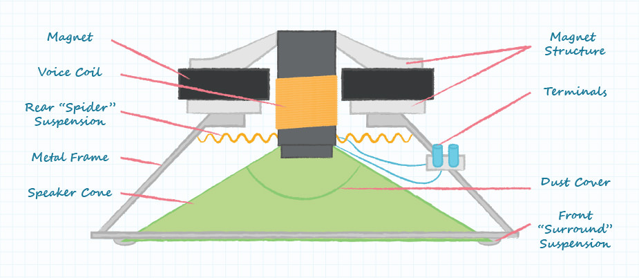
As mentioned, standard speakers have a cone connected to a frame via a suspension. There is also an electromagnet magnet attached to the rear of the cone that affects the weight. Depending on the material used for the cone, the thickness of the suspension, and the size of the electromagnet, the resonant frequency will vary. Typically, lighter yet stiffer materials and more flexible suspensions yield higher resonant frequencies. For this reason, high frequency tweeters are small, thus light, and generally have rigid mylar cones and very flexible suspensions. In general, by modifying these factors, standard speakers have a frequency range somewhere between 20 Hz and 20,000 Hz.
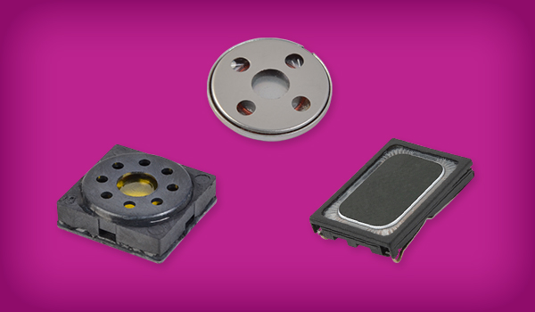
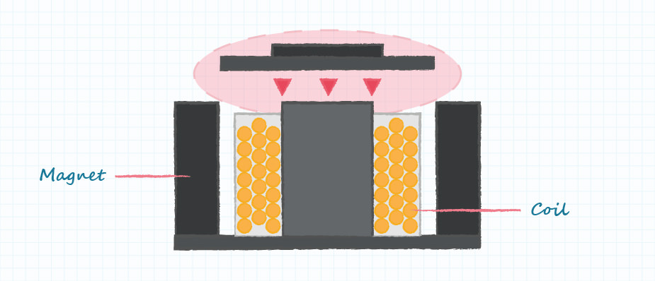
Magnetic transducer buzzers are another audio device, but they separate the driving mechanism from the sound producing mechanism differently than a standard speaker. The diaphragm is lighter and also attached in a more rigid manner to the frame, which drives their normal frequency range higher and also reduces their range. Magnetic transducer buzzers usually produce sound in the 2-3 kHz range and don’t require as much current as a standard speaker for the same SPL.
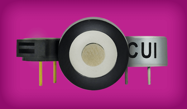
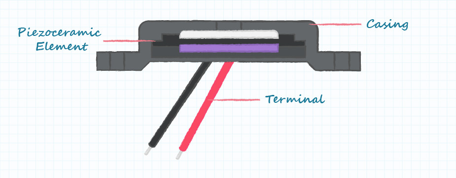
Finally, piezoelectric transducers are a third way to generate sound. They use the piezoelectric effect, using a varying electric field to cause the material to bend first one way and then another. Piezo materials are typically quite stiff, and the pieces used in piezoelectric transducers are quite small and thin. Because of this, similar to the magnetic transducer buzzers, they produce a high pitched noise, typically between 1 and 5 kHz, with a narrow frequency range. They are even more efficient than the magnetic buzzers, as they generally produce an even higher SPL than the magnetic buzzers with the same amount of current.
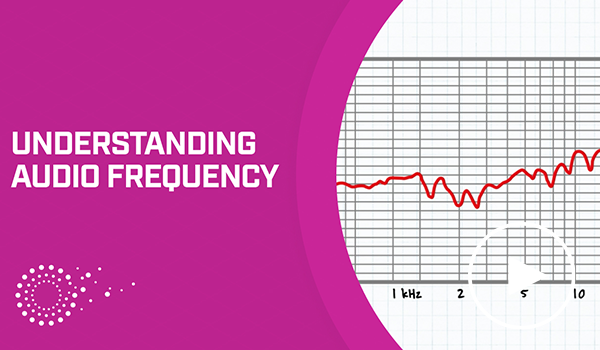
Reading Resonance in Frequency Response Curves
While it is possible to run tests to determine the resonant frequency of an audio device, it is usually not necessary. Most manufacturers provide a graph of SPL versus frequency on the datasheet that shows the resonant frequency along with overall frequency response. However, manufacturers cannot account for any change in this resonant frequency specification due to the mounting, enclosure size, construction, and material used to integrate an audio device in an overall system. Despite this, they are a helpful resource to provide a starting point for selection and design.
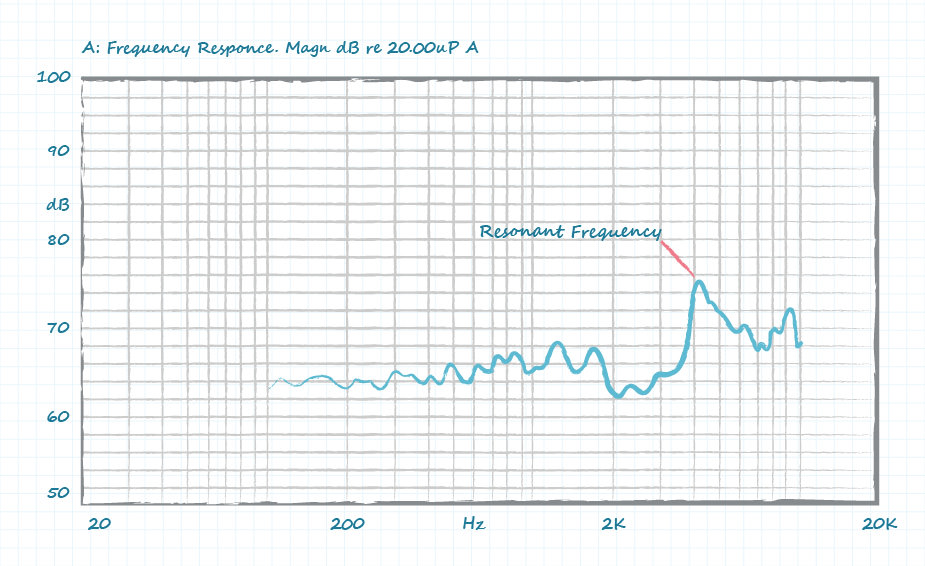
Below is an example of the frequency response graph for the CMT-4023S-SMT-TR magnetic transducer buzzer. Its datasheet lists a resonant frequency of 4000 Hz, which is clearly indicated by the peak shown on its frequency response chart.
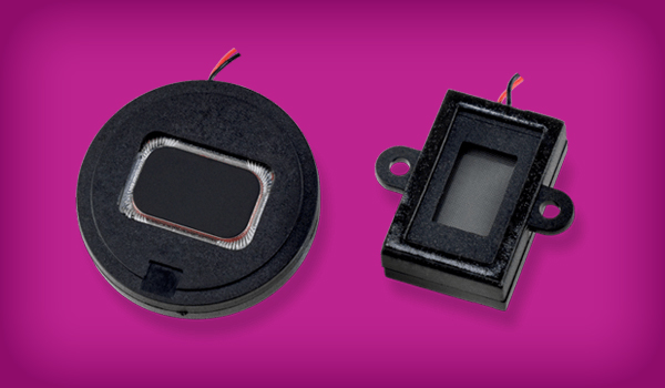
Audio indicators, using either magnetic and piezoelectric technology, are also an option. Due to their built-in drive circuitry, these internally driven devices have no need for a frequency response graph, as their operation is at a fixed, rated frequency. They are designed to maximize SPL in that frequency window and simplify resonance issues.
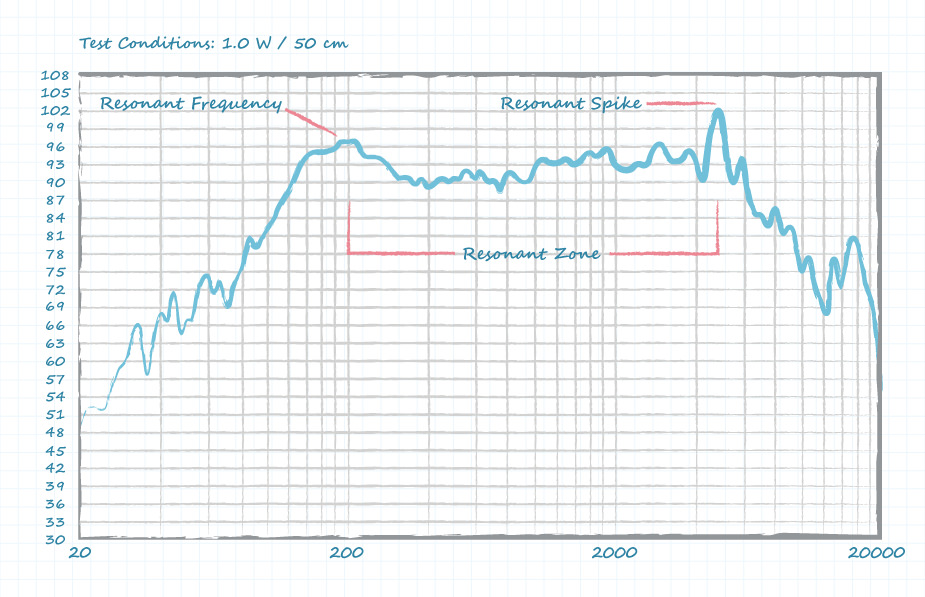
As another example, the CSS-10246-108 speaker lists a resonant frequency of 200 Hz ± 40 Hz on its datasheet, but its frequency response graph also shows another resonant spike at roughly 3.5 kHz as well as a resonant zone from approximately 200 Hz to 3.5 kHz.
Overall, each audio device will have frequencies where it will amplify sound and frequencies where it will reduce or attenuate sound. By driving a buzzer or speaker with an input signal that has a frequency at or near the audio device’s resonant frequency or resonant zones, designers can create the greatest SPL with the least input power. However, most applications do not operate at just one frequency. While the resonant frequency is where the maximum SPL is achieved, a speaker or buzzer can be used across the frequency range per its specification, provided the SPL is sufficient for the intended application.
Resonance Design Challenges
Once designers know the resonant frequency of a device, they have two challenges remaining with respect to resonance: first, making use of the inherent resonant frequency and resonant zone to maximize SPL, while secondly, avoiding undesired buzzing and rattling in the installation due to resonance-induced effects.
While due diligence and rough assessments are important in the up-front design phase, there is no substitute for building a prototype and using trial-and-error to empirically produce the optimal enclosure for the specific audio source. Any implementation must also consider the range of component tolerances and production variations.
Further, particularly for speakers, it is important to ensure that there is sufficient cubic volume in the enclosure so audio output is not attenuated due to lack of space for the audio energy to be distributed. Even a modest 3-dB reduction in SPL caused by the enclosure covering or materials corresponds to a 50% decrease in output sound power. Our blog, “How to Design a Micro Speaker Enclosure” provides helpful insights on this issue and tips on proper enclosure design.
Overall, it is important to look at the full-spectrum response of the audio device and utilize the broader range of frequencies on either side of resonant frequency. The ultimate design objective is to optimize output SPL and frequency for a given power delivered to the buzzer or speaker. To achieve this, the frequency at which the device is being driven should be matched to the resonance as well as the broader response spectrum. Keep in mind that resonant frequency is not an exact number nor is it necessarily narrow, so there will likely be a desirable response on either side of the number specified on a datasheet.
Conclusion
When designing an audio device and its output into an application, engineers must take into account the device’s resonant frequency to ensure that the end product maximizes SPL while avoiding undesirable buzzing and rattling. This requires the use of vendor-supplied numbers, particularly the resonant frequency, then optimizing the design across the resonant zone above and below this value. Once the initial design is completed, a hands-on verification of the interaction between enclosure and mounting should be performed to confirm theoretical calculations. The result will be an audio output which meets product objectives by satisfying both the user and manufacturing requirements.
 Tags:
Tags:
Additional Resources