RS-485 Serial Interface Explained
With a world of serial interfaces available, it can be hard to understand their differences and when to use each one. As my favorite engineering professor would always say, “The wonderful thing about standards is that there are so many of them to choose from.” Encoders today are smarter and more advanced than ever before requiring engineers to abandon simpler quadrature incremental sensors and adopt high speed absolute encoders with serial interfaces. And for applications in the industrial space, not all serial interfaces are created equal. Fitting the bill for both high speed and industrial robustness, the RS-485 serial interface has become a widely implemented interface for rotary encoders and other motion control equipment.
What is RS-485?
RS-485 is an industrial specification that defines the electrical interface and physical layer for point-to-point communication of electrical devices. The RS-485 standard allows for long cabling distances in electrically noisy environments and can support multiple devices on the same bus.
When, Why, and Where to Use RS-485
RS-485 has been used in a wide range of computer automation systems dating back to when the standard was created in 1998. With the standard allowing for multi-drop (multiple devices on the same bus) and long cabling lengths, it is easy to understand its frequent use in the industrial and automation spaces. RS-485 can also be found in theater applications where many devices are spread out across a huge space.
In addition, the noise immunity offered by the RS-485 standard makes the interface very versatile. Engineers are not only using it for long cabling distances, but are implementing it into applications, such as the automotive industry, where it is uncertain what noise could be encountered in the end application. The ability to use RS-485 at high speeds, over long cabling lengths, in electrically noisy environments, and with multiple devices on the same bus, makes it a smart implementation for most applications requiring a serial interface.
The RS-485 Standard
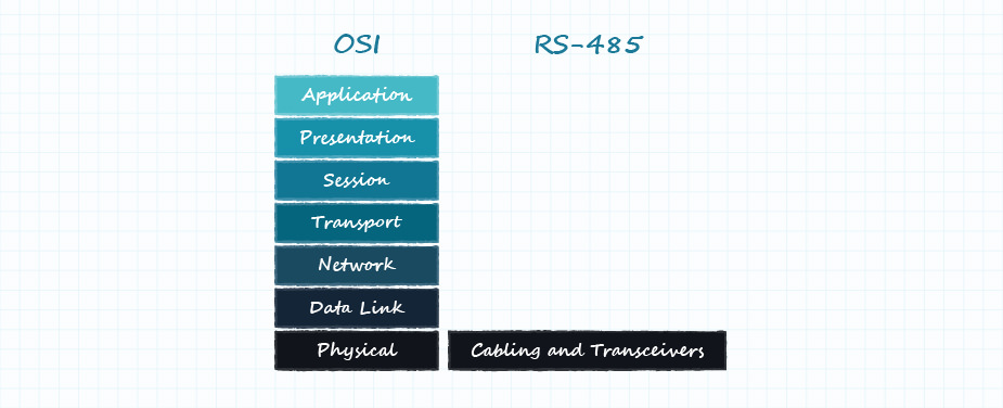
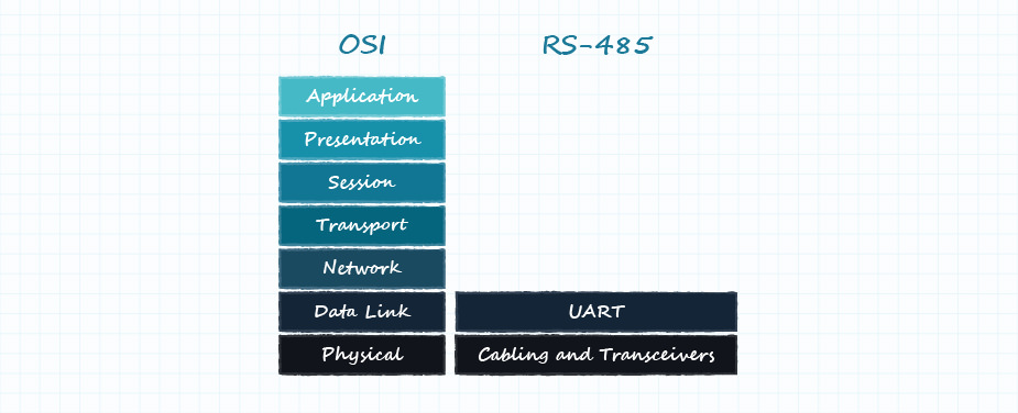
RS-485, also known as TIA-485 or EIA-485, is the standard that defines the electrical characteristics of the drivers and receivers for the communication protocol. The Open Systems Interconnection (OSI) model attempts to characterize the various layers of a communication system from final application, down through the electrical layers, and lastly onto the physical layer, Figure 1.

Physical Layer of the OSI Model
The physical layer of the OSI model is responsible for the transfer of raw data between a device and a physical transmission medium. It handles the conversion of electrical signals into digital data, while defining voltages, timing, data rates, etc.
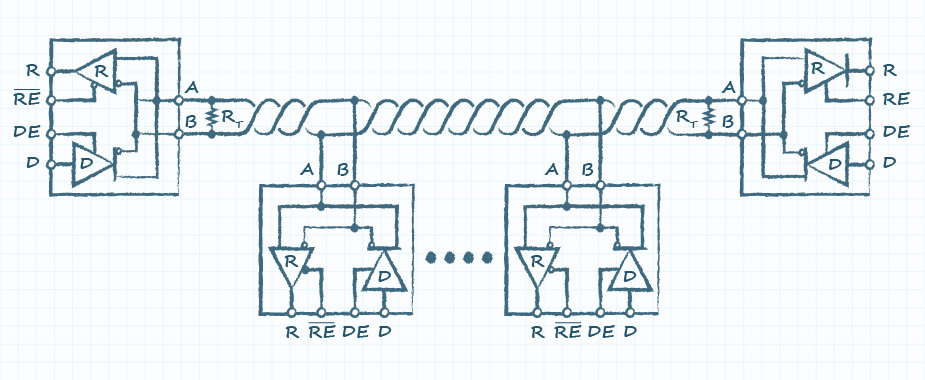
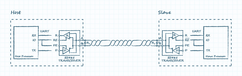
RS-485 uses two signal lines, ‘A’ and ‘B’, which must be balanced and differential. Balanced signals are two lines that share a pair in a twisted pair cable with the same impedance on each line. Along with matched impedance of the lines, there must also be matched impedance at the receiver and transmitter. Figure 2 shows a typical multi-drop RS-485 network where each device has a differential RS-485 transceiver and the link between devices is comprised of twisted pair cabling and termination resistors.
Note, there are various topologies that can be used to arrange devices because not all networks are created equal and termination requirements as well as device arrangement will vary. For example, in Figure 2 below termination is only used at the beginning and end of the cable.
Balanced cabling allows for noise reduction when using differential signals. These signals, ‘A’ and ‘B’ are referred to as a differential pair; one of the signals matches the original signal, while the other is entirely inverted, which is why it is sometimes referred to as a complementary signal.
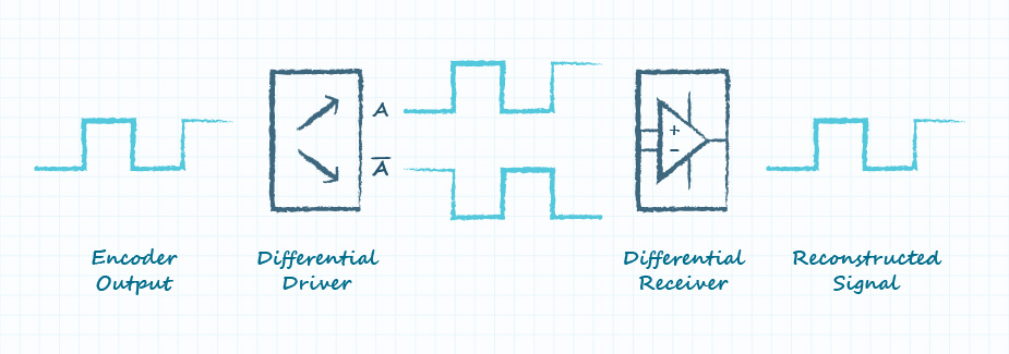
In a single-ended interface, the receiver references the signal to ground, and resolves the signal state based on predetermined voltage levels (these are referred to as logic levels as they determine if the signal is logic high or logic low). However, over long cabling distances where voltages tend to drop and slew rates decrease, signal errors often occur. In a differential application, the host generates the original single-ended signal, which then goes to a differential transmitter. This transmitter creates the differential pair to be sent out over the cabling. With two signals generated, the receiver no longer references the voltage level to ground, but instead references the signals to each other. This means that rather than looking for specific voltage levels, the receiver is always looking at the difference between the two signals. The differential receiver then reconstructs the pair of signals back into one single-ended signal that can be interpreted by the host device using the proper logic levels required by the host, Figure 3. This type of interface also allows devices of differing voltage levels to operate together by way of communication between the differential transceivers. All this works together to overcome the signal degradation that would have occurred with a single-ended application over long cabling distances.
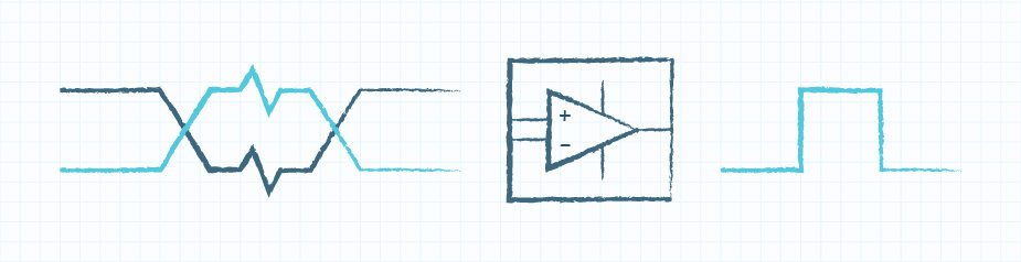
Signal degradation is not the only issue that arises over long cabling distances. The longer the cabling is within a system, the higher the chances that electrical noise and interference will make its way onto the cables and ultimately into the electrical system. When noise couples onto cabling it shows up as voltages of varying magnitudes, but the benefit of using a balanced twisted pair cable is that the noise couples to the cable equally on each line. For instance, a positive 1-volt spike would result in +1 V on A and +1 V on B. Because the differential receiver subtracts the signals from each other to get the reconstructed signal, it would ignore the noise shown equally on both wires, Figure 4. The ability of the differential receiver to ignore voltages that are the same on both signal lines is referred to as common mode rejection.
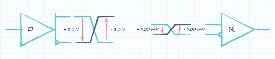
One of the other major physical layer benefits of RS-485 is the signal voltage specification. RS-485 does not require the use of a specific bus voltage, but instead specifies the minimum required differential voltage, which is the difference between the signal A and B voltages. The bus requires a minimum differential voltage of +/- 200 mV at the receiver and generally all RS-485 devices will have the same input voltage range despite transmitting at various voltages. This means that any RS-485 device is able to receive the voltage range of -7 to 12 V, so an engineer can design the host system with any transmission voltage in that range. This allows designers to create RS-485 systems using their existing board voltages.
With that being said, it is important to verify the product specifications to ensure that the device supports the full voltage range of the standard. For example, CUI Devices’ RS-485 encoders use 3.3 V on the board, so they use an RS-485 3.3 V transmitter. However, they are also input tolerant between 0 and 12 V. This allows them to share the same RS-485 bus at multiple different transmission voltages between 0 and 12 V without issue if the minimum differential voltage of +/- 200 mV can be met at both the receiver and the transmitter. This is especially important because as cable length increases, so does the voltage drop on the signal lines. A host device may transmit with a differential voltage of +/- 1 V but over a long cable length that voltage could diminish down to +/- 200 mV, which is still perfectly acceptable for RS-485, Figure 5.
Data Link Layer of the OSI Model
RS-485 is a duplex communication system in which multiple devices on the same bus can communicate in both directions. RS-485 is most often used as half-duplex, as shown in the figures above, with only a single communication line (‘A’ and ‘B’ as a pair). In half-duplex, devices take turns using the same line where the host will assert control of the bus and send a command with all other devices listening. The intended recipient will listen for its address and then that device will assert control and respond back. Conversely, in a full-duplex system, such as Serial Peripheral Interface (SPI) or Universal Asynchronous Receiver Transmitter (UART), host and slave devices can communicate at the same time using dedicated input and output lines.
At the data layer RS-485 generally uses a UART for serial communication where the host UART drives and receives the serial communication in full duplex. It is connected to the RS-485 differential transceiver that makes up the physical layer and converts the signals into the half-duplex differential format for use on the RS-485 bus. The host will then communicate with the RS-485 through the UART, and it will tell the transceiver when to switch between transmit and receive. Slave devices will also use their UART in the same way.
UART having dedicated transmit and receive lines allows it to operate as full-duplex, half-duplex, or even simplex, which means data only ever goes out or comes in on one line. Since RS-485 is typically half-duplex, the UART connected to it will also operate at half-duplex.
A UART interface is asynchronous which means that the communication does not include a clock. The host and slave devices must use their own internal clocks, and both devices must know at which clock-rate the data will be transmitted. This differs from a synchronous system such as Serial Peripheral Interface (SPI) where one of the signal lines contains a clock on which the listening device on the bus can capture data.
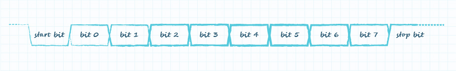
In addition, the UART generally has a normal format that most devices will use, but many options can be configured to change the norm. The idle state of UART is voltage high, so to begin transmission the UART uses a low pulse called a start bit, followed by 8 bits of data, and is completed with a high stop bit, Figure 8.
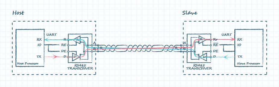
The host processor will use an IO pin to put the RS-485 transceiver in transmit mode, and it will send a byte from the UART TX line to the RS-485 transceiver’s Data (D or DI) line. The transceiver will convert the single-ended UART bit stream into a differential bit stream on the A and B lines, Figure 3. Immediately after the data leaves the transceiver, the host switches the mode of the transceiver to receive. The slave system is identical, meaning that the slave RS-485 transceiver receives the incoming bitstream, converts it to a single ended signal, and sends it to the host device via the slave’s UART RX line. When the slave is ready to respond, it transmits as the host did originally while the host now receives, Figure 9.
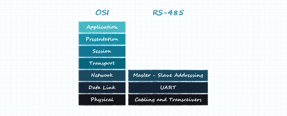
Network Layer of the OSI Model
The network layer deals with the actual communication between devices that occur on the RS-485 bus. Because RS-485 is mostly an electrical specification, the conversation could end here, but as it supports multi-drop, there is a need to address it in the OSI model.
There is no set specification for addressing the network layer, but the RS-485 bus must be properly managed by a master to avoid bus collisions. Bus collisions occur when multiple devices attempt to communicate at once, which can be very harmful for the network. When collisions occur, transmitters clash on both ends and effectively both create shorts. This causes each device to draw large amounts of current that could put the transceiver into thermal shutdown.
To avoid collisions, the master controls the bus and will make calls to individual devices. This is most often accomplished by having a command set that only specific devices recognize, or by having specific addresses for each device. Since the bus is shared between all devices, every device will see the command/address being sent by the master but will only respond when that individual device is asserted.
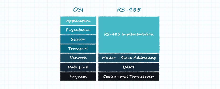
Application Layer of the OSI Model
The OSI model is not a set of rules but more of a model that helps engineers characterize systems. RS-485 is well-contained within the first three layers of the OSI model with the actual implementation of the bus being characterized within the application layer. This layer covers the addresses or command sets used by the devices as well as the interpretation of the data. It also includes how much data a designer could expect to get back, and the control of the bus itself.
For instance, the application for a CUI Devices RS-485 encoder would be the host requesting absolute position from the device. When the host sends the encoder’s position command (address), the encoder responds with two full bytes. The host then deciphers those bytes to understand what the absolute position is, while making determinations on how often to send commands and to which devices it wants to send them. Simply stated, the application layer is the implementation of the RS-485 bus.
Because the RS-485 standard only defines the physical and data link layers with an addressing requirement, the application layer can adopt various proprietary or open communication protocols. Engineers can adopt existing protocols, such as Modbus, or they can define their own for their application. For example, CUI Devices’ encoders use a very simplified addressing structure for asserting devices that allows for fast turnaround and minimal processing times. Each encoder’s address is only the upper six bits in a byte, with the lower two bits being the command. This allows the encoder to begin its response after only a single byte from the master that ensures a fast turnaround time which is critical in motion control applications.
CUI Devices’ RS-485 Encoders
CUI Devices’ RS-485 encoders use a fast position protocol that allows the encoder to respond with position within a byte’s time. As described above, this format supports 64 unique encoder addresses. The encoder’s address is the upper 6 bits in a byte, with the lower 2 bits being the command. These addresses are configurable via CUI Devices’ AMT Viewpoint™ software and a programming module. These encoders have various commands depending on their version, with all devices supporting extended commands such as reset, or set zero position.
| Low Two Bits | Hex | Command |
|---|---|---|
| 00 | 0x00 | Read position |
| 01 | 0x01 | Read turns counter (multi-turn encoders only) |
| 10 | 0x02 | Indicates extended command |
| 11 | 0x03 | Reserved |
CUI Devices’ absolute encoders feature 12-bit or 14-bit resolutions, however, all of them respond with two full bytes for every position request. Two full bytes is 16 bits, which allows the encoder to use the upper two bits for a checksum calculation. This part of the application layer allows the host to validate the transmitted data from the encoder. For 12-bit encoders, the transmission will have the check bits in the upper two bits, with the lower two bits being zero and the 12 bits in-between containing position data.
These absolute encoders are also available with multi-turn support so that they can count the number of revolutions. This is a 14-bit signed counter and data is transmitted the same as position with the top two bits containing the checksum. Because the counter is signed, it can count positive and negative turns but at the expense of one bit of data. This means it can count from -8192 to 8191.
CUI Devices’ absolute encoders are further available in a high-speed version that operates at 2 Mbps with turnaround times close to 3 microseconds. However, for applications that cannot manage the high-speed and tight timing requirements, adjustable data rate versions are available. These versions give users the option to select from a list of frequencies using the AMT Viewpoint and a programming module, allowing for easier implementation when high speed is not necessary.
Conclusion
Supporting high speeds, long cabling distances, electrical noise tolerance, and multiple devices on the same bus, RS-485 has become a popular serial interface in rotary encoders due to its versatility in a wide range of applications. Designers looking to utilize encoders with an RS-485 interface can benefit from an understanding of the details outlined above, including its various layers, implementation, and best practices in overall system communication. Offering added ruggedness and industrial robustness, CUI Devices’ capacitive-based AMT absolute encoders with RS-485 interface are an intriguing option for motion control applications due to their high accuracy, low current draw, and immunity to environmental contaminants.
 Tags:
Tags:
Additional Resources